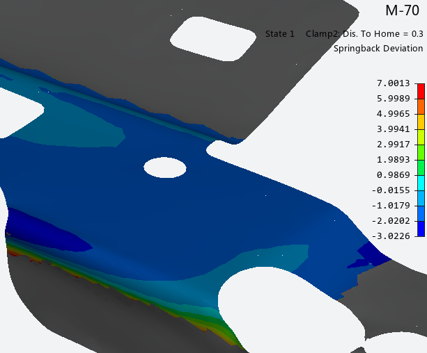
The springback evaluation diagram enables you to view calculated springback data, and measure springback data by comparing the simulated part shape to a reference shape. Either the upper or lower surface of the simulated part can be compared. Tool meshes are often used as a reference shape. Choose from the Analysis Ribbon Elements to display the Springback Evaluation task panel and view a diagram of the springback in the part.
Choose an Operation from the first drop-down menu in the Part Shape to be Evaluated section. Only the operations for which you checked the Springback check box will be available. If you configured a Measurement operation to the end of the process, it will also be available. Choose a measurement from the second drop-down menu. For most operations, the only measurement available will be . If you configured Clamps or Nets for a Measurement operation, choose the desired option from the second menu. Click a time or distance in the list below the drop-down menu to select it for viewing.
In the Options section, choose whether or not to compare the final shape to the Initial Shape. If the reference shape does not represent the middle of the actual part, check the Part Shape Offset To check box and choose if the reference shape represents the or of the actual part. This will offset the simulated part shape to match the desired side of the actual part before performing the comparison.
The current reference shape is shown in the text field of the Reference Shape section. Choose a different reference shape by clicking the button and selecting an imported mesh from the Pick Reference Part task panel. Display the reference shape in the graphics window by checking the check box.
You can choose a part reference when you define a measurement operation. Meshes chosen at that time are automatically made available to postprocessing. Surfaces chosen at that time are used to create meshes, and the meshes made available to postprocessing with names that start with "RefMesh_". If you redefine the part reference after running the simulation, you will need to use the command to load the new reference data. for more information, see Updating Results.
The Settings section enables you to match the positions of the reference shape and part shape. Choose or from the drop-down menu. Then, choose a location method from the Located by drop-down menu. When you choose a method, a Part Locating task panel enables you to define the details of your chosen method. To (in addition) have the software find the best fit between Part and Reference, check the box next to Best Fit. This option is valid even if you choose the method .
Further configure the display of the springback diagram using the options in the Settings section. Choose a category of displacement data from the drop-down menu. Choices may include , , and depending on which measurements have been defined in the simulation. Other options in the Settings section change based on the category you choose.
When springback evaluation settings are configured or changed, the button is active. Click to calculate springback values and display them on the model.
Click to use the List Value Task Panel to pick points to display the numerical values at those points on the plot.
Click to use the Contour Setting Task Panel to modify the settings of the plot contours.
When you are finished with the Springback Evaluation plot, click .


