These capabilities are available to you while you are using any of the following postprocessing tools.
If you are using the postprocessing tools and the simulation results change, either because the simulation is still running or has been re-run while the analysis tools are open, the software displays a notice that the data you are currently analyzing are out of date and should be updated.
On the ( ) menu, use the
command to load the new simulation
results. This will not change the view, your zoom and rotation settings will be
preserved.
Use the View Tools on the ribbon or the commands on the graphics window's context menu to change views of the results. This can be helpful to make results visible that would otherwise be hidden by other parts of the workpiece.
During postprocessing, the context menu contains the commands and . Use to copy the current view settings to the clipboard. You can modify the view settings to explore the reults, then use to return to the original settings. You can also paste the view settings into other panes of the graphics window to compare the same view of other projects or copies of this project.
Choose from the ( ) drop-down menu in the main
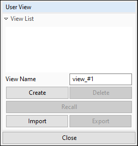
toolbar to open the User View Task Panel. Use it to
create, delete, recall, import, and export user view settings.

To create a new view from the current view settings, enter a meaningful name in the View Name field and click . This adds the name you entered to the View List.
To apply a view from the list to the graphics window, click the view's name in the View List to select it, and click .
To save a view in the View List to a View Data File:
Click the view's name in the View List to select it.
Click to open a file browser.
Navigate to a memorable location. It is best to use a central location, and not a specific project directory.
Enter a File name, and click .
To load the exported view into another project:
Open the other project.
Click to open a file browser.
Navigate to the location of the View Data File (this will be a .xml file) and select it.
Click .
The View List shows the saved view, and it can be selected and recalled into the current graphics window.
When you are finished with the User View task panel, click to remove it from the window.
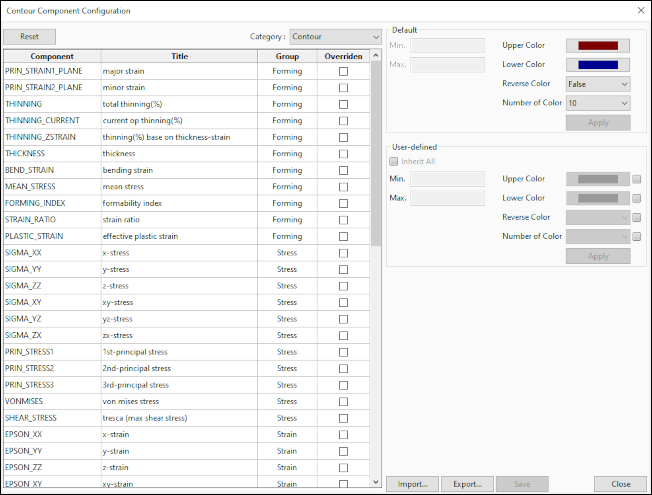
Whether for printing clarity, personal preference, workplace style guidelines, or customer requirements, you may wish to change how data values are displayed in analysis plots. The Contour Component Configuration interface enables you to change the color settings used to display data in Contour, Vector, Contact, and Curvature plots. Settings may be changed at the global level, and at the component data level.
Note that when you are changing the upper and lower colors using this window, you are not changing the color gradient end colors, you are only changing the colors used to display values that are above the maximum or below the minimum. Set the Max. value to slightly lower than the actual maximum value and the Min. value to slightly higher than the actual minimum value, or data at those precise values will not display using the custom colors.

At any time while modifying component configurations, you may click the button in the upper-left corner of the dialog to discard all changes and return to default configurations.
To change the contour component configuration:
If you have the Contour Setting Task Panel open, you must close it before continuing.
On the (
 ) menu, choose +Contour Component.
In the Contour Component Configuration dialog, choose a Category from the drop-down menu.
Select a component in the table.
Click configuration values to modify them.
Click .
Click to record the new settings in the project database.
To save the current setting to an external file, click .
To load settings that were exported from another project into the current project, click .
Click .
Note: You cannot use this dialog to modify the configuration of FLD plots. Modify the display of these
components in the > section of the System Configuration panel.
Choose > from the ( ) menu to access this
panel.
Once you have exported a well-defined configuration file, you can make this configuration the default for all Forming users on the local computer or network. When you launch Forming, if no local configuration file is found in the Forming directory of an installation, the public configuration file will be used. If a local configuration file is found, custom settings in the public file will override settings in the local file, but default settings in the public file will not override custom settings in the local file.
To make the exported contour component configuration a shared default:
Move the exported configuration file to a shared directory on the local machine, or a shared network folder.
On the (
 ) menu, choose +System.
Scroll down to > and select .
In the Option Grid, double-click the field next to location.
Enter a full directory path (including the drive letter) or full network path of the shared folder.

Click .
Click .


