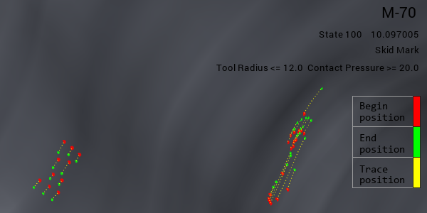
Skid lines show the elements that pass through regions with a small radius. Those elements tend to have surface smoothness problems, since they experience large bending and unbending deformation under high pressure. These are often considered to be flaws that require re-finishing of the surface. The skidmark function displays a skidmark plot based on contact between the blank and a tool at a predefined line, and the movement of this material during a following drawing process. Choose from the Analysis Ribbon Elements to display the Skidmark task panel and view the plot in the Graphics Window.
Use the Skidmark task panel to select individual operations to view, or to play an animation of the forming process. You must have more than one operation selected to view the animation.
Modify Threshold Parameters and click to display contact lines on the project. If the threshold radius is greater than the tool radius value, and the threshold contact pressure is less than the local contact pressure in the simulation, there will be scratches on the finished part. Your experience will inform you regarding what combinations of radius, pressure, and material are likely to result in marks on the finished part.
To display only scratches created during the current operation, check the box next to Show Current OP Only. To display only scratches caused by the upper tools or lower tools, select the appropriate radio button, or select to display all scratches.
Click to write the selected contact lines to an IGES file. You can import these lines into other sessions or projects using the Import tool on the ribbon so that you do not have to draw them again.
When you are finished with the skid mark plot, click the button to return to Viewing Basic Deformation Results.


