


The workspace provides a convenient way to set up the most common materials processing simulations through the use of specialized wizards.
Start the workspace.
Read in a mesh (either a Fluent or a Polyflow mesh file).
Note: When the Fluent Materials Processing workspace reads in a mesh, all topological names (later referenced by the wizard) are changed to lower case.
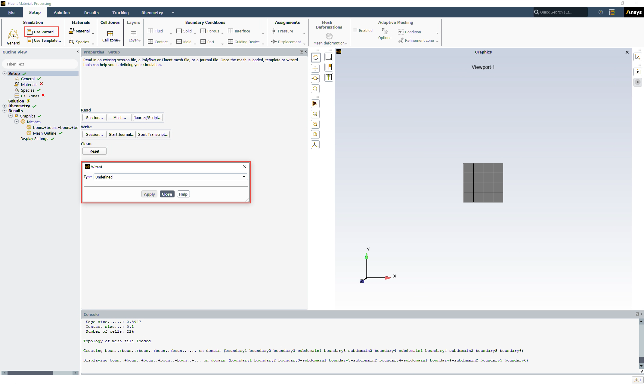
Click the Use wizard... button, under the Simulation category, in the Setup Ribbon. This displays the Wizards dialog.
In the Wizards dialog, select an appropriate Type. Depending on the mesh topology, you can choose from:
This wizard is available for you to quickly set up and solve a simple internal flow problem for a given mesh. The wizard expects a particular topology as described in Expected Topology for the Simple Internal Flow Wizard.
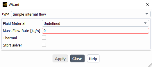
Specify a Fluid Material.
Provide a value for the Mass Flow Rate.
Enable the Thermal option if temperatures are important in your simulation, in which case, you can then provide the Inlet Temperature and the Wall Temperature.
Use the Start solver option to automatically start solving the simulation once the simulation has been set up.
If this option is enabled, once you click Apply and leave the wizard, the workspace takes your settings and sets up the simulation accordingly and solves the problem automatically. Once the calculations are completed, you can easily proceed to analyze the results.
The Simple Internal Flow Wizard requires a simple topology which includes an inlet, an outlet, one or several walls and possibly one or several symmetry planes, as suggested in Figure 4.35: Boundary Zones for Simple Internal Flow.
As such, when using the wizard, zones are expected to have specific names:
| Role in the Wizard | Recommended Zone Name | |
|---|---|---|
| Zones | fluid-zone | Any zone name |
| Boundary Zones | inlet | inlet |
| outlet | Any boundary name(s) containing
exit | |
| symmetry | Any boundary name(s) containing
symm | |
| wall | Any boundary name(s) containing
wall |
This wizard is available for you to quickly set up and solve a direct extrusion problem for a given mesh. The wizard expects a particular topology as described in Expected Topology for the Simple Direct Extrusion Wizard.
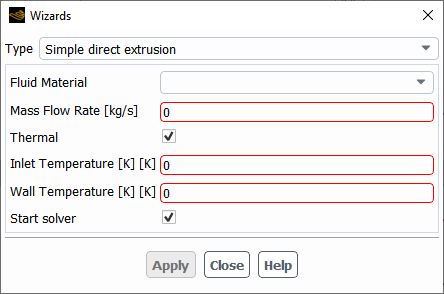
Specify a Fluid Material.
Provide a value for the Mass Flow Rate.
Enable the Thermal option if temperatures are important in your simulation, in which case, you can then provide the Inlet Temperature and the Wall Temperature.
Use the Start solver option to automatically start solving the simulation once the simulation has been set up.
If this option is enabled, once you click Apply and leave the wizard, the workspace takes your settings and sets up the extrusion simulation accordingly and solves the problem automatically. Once the calculations are completed, you can easily proceed to analyze the results.
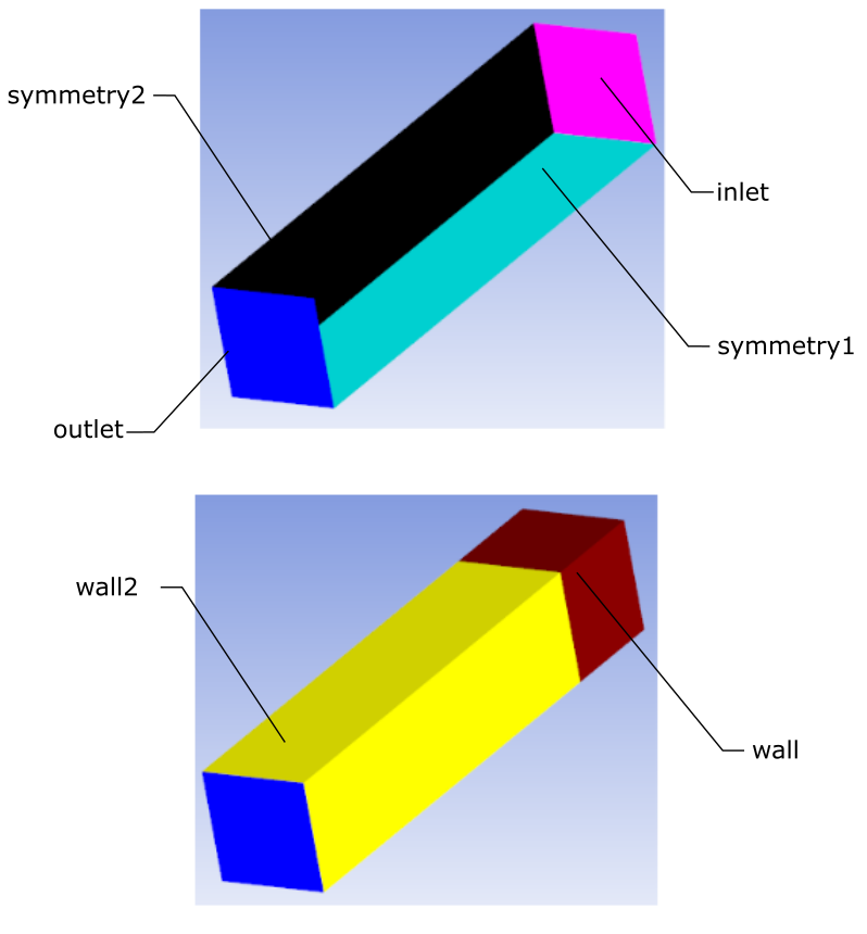
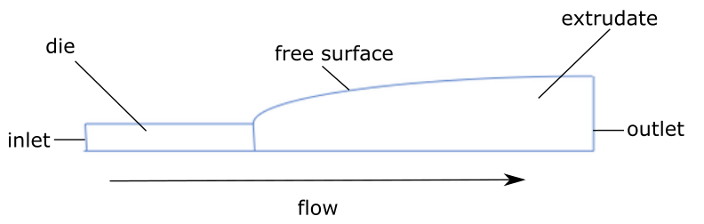
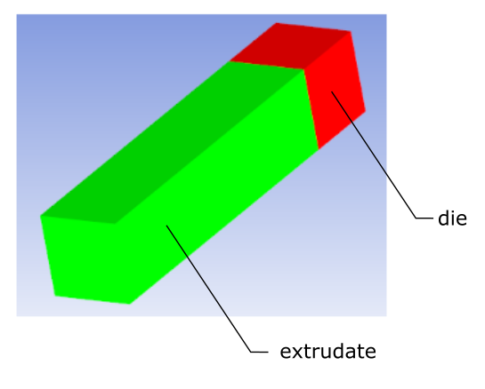
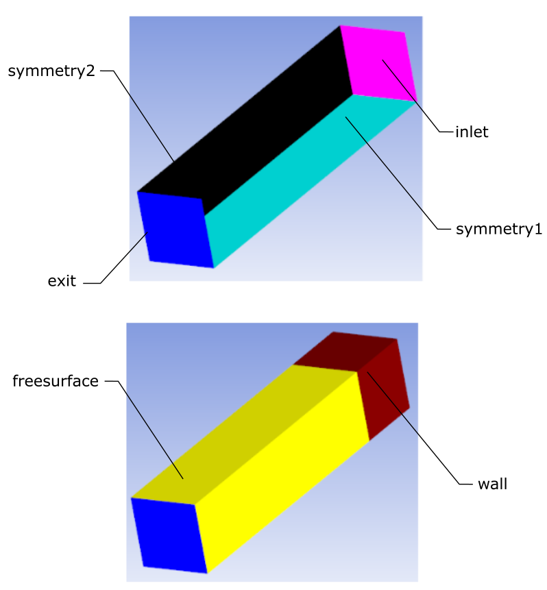
The Simple Direct Extrusion Wizard requires a topology which includes specific zones and boundaries: required zones are a die channel and an extrudate; required boundaries include an inlet, an outlet, one or several walls, free surface(s), and possibly one or several symmetry planes, as suggested in the following figures:
As such, when using the wizard, zones are expected to have specific names:
| Role in the Wizard | Recommended Zone Name | |
|---|---|---|
| Zones | die | die |
| extrudate | extrudate | |
| Boundary Zones | inlet | inlet |
| first symmetry plane | symmetry1 | |
| second symmetry plane | symmetry2 | |
| die walls | wall | |
| free surface | freesurface | |
| extrudate-exit | exit |
Note: In general, all boundaries containing "symm" will be considered as symmetry boundaries, all boundaries containing "wall" will be considered as wall boundaries, and all boundaries containing "freesurf" will be considered as free surface boundaries, however, a single boundary must be named "exit" for the extrudate exit, and a single boundary must be named "inlet" for the inlet condition. Symmetry boundaries are, of course, optional, and while these boundaries may or may not exist, the workspace will use them if present.
This wizard is available for you to quickly set up and solve an inverse extrusion problem for a given mesh. The wizard expects a particular topology as described in Expected Topologies for the Simple Inverse Extrusion Wizard.
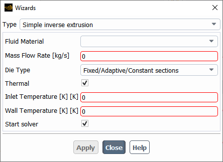
Specify a Fluid Material.
Provide a value for the Mass Flow Rate.
Specify the Die Type. The wizard requires a specific topology, depending on the specific combination of included sections. See Expected Topologies for the Simple Inverse Extrusion Wizard for more information.
Enable the Thermal option if temperatures are important in your simulation, in which case, you can then provide the Inlet Temperature and the Wall Temperature.
Use the Start solver option to automatically start solving the simulation once the simulation has been set up.
If this option is enabled, once you click Apply and leave the wizard, the workspace takes your settings and sets up the extrusion simulation accordingly and solves the problem automatically. Once the calculations are completed, you can easily proceed to analyze the results.
The Simple Inverse Extrusion Wizard requires a specific topology, depending on the specific combination of included sections.
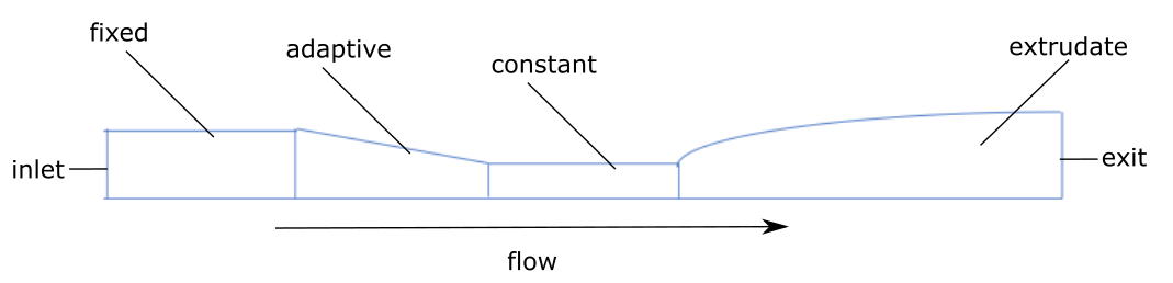
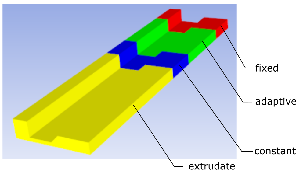
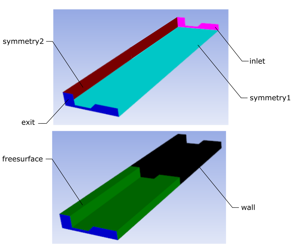
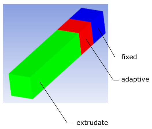
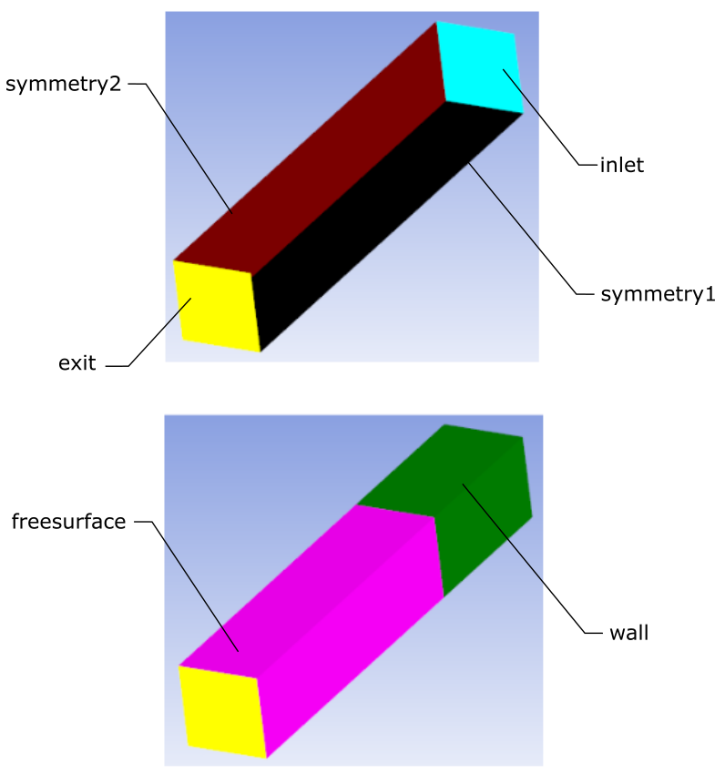
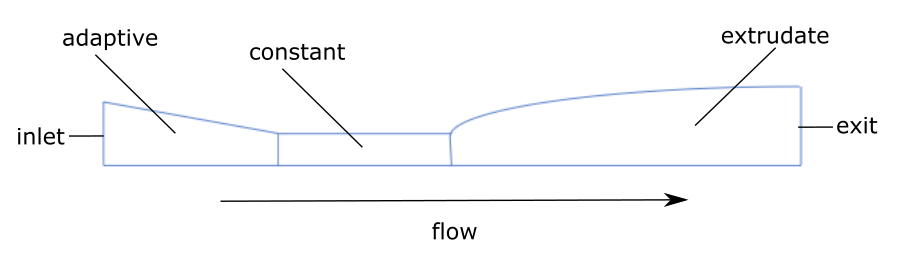
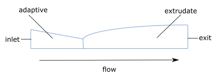
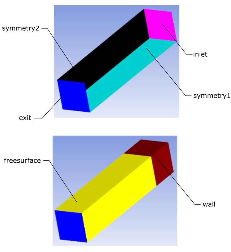
For fixed/adaptive/constant section configurations, the Simple Inverse Extrusion Wizard requires a topology which includes specific zones and boundaries. Required zones are a die channel made of a fixed, an adaptive and a constant section, as well as an extrudate. Required boundaries include an inlet, an outlet, one or several walls, free surface(s), and possibly one or several symmetry planes, as suggested in the following figures:
As such, when using the wizard, zones are expected to have specific names:
| Role in the Wizard | Recommended Zone Name | |
|---|---|---|
| Zones | fixed part of the die | fixed |
| adaptive part of the die | adaptive | |
| constant part of the die | constant | |
| extrudate | extrudate | |
| Boundary Zones | inlet | inlet |
| first symmetry plane | symmetry1 | |
| second symmetry plane | symmetry2 | |
| die walls | wall | |
| free surface | freesurface | |
| extrudate-exit | exit |
Note: In general, all boundaries containing "symm" will be considered as symmetry boundaries, all boundaries containing "wall" will be considered as wall boundaries, and all boundaries containing "freesurf" will be considered as free surface boundaries, however, a single boundary must be named "exit" for the extrudate exit, and a single boundary must be named "inlet" for the inlet condition. Symmetry boundaries are, of course, optional, and while these boundaries may or may not exist, the workspace will use them if present.
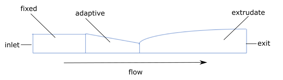
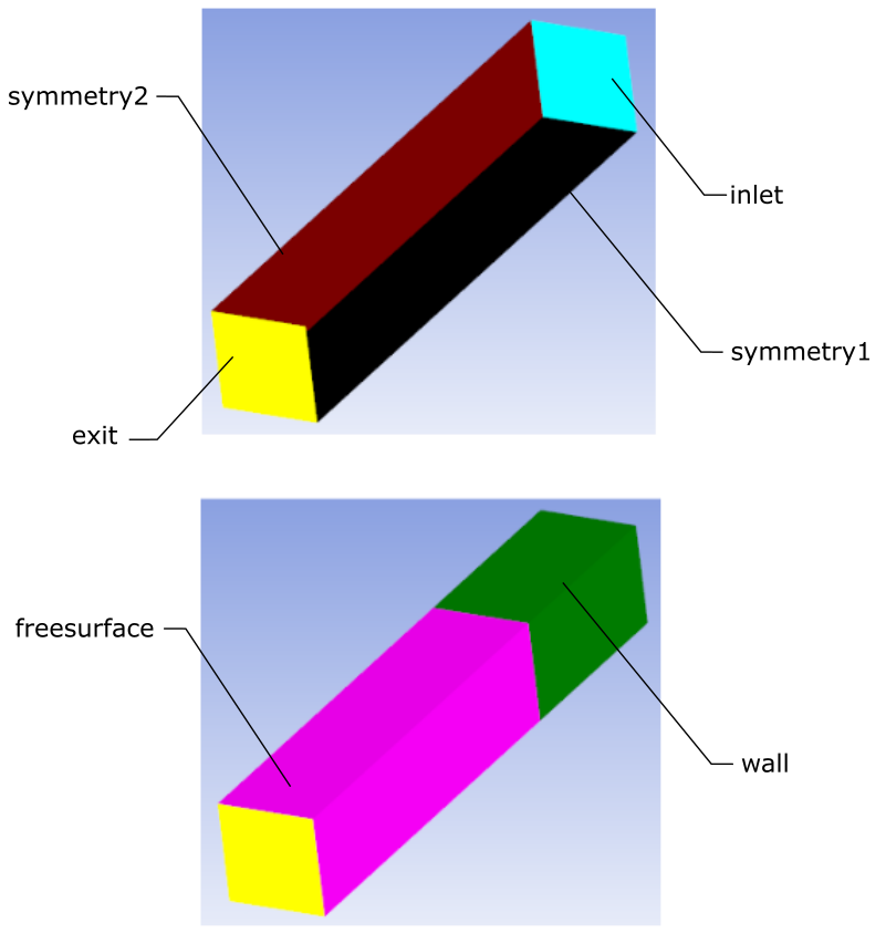
For fixed/adaptive section configurations, the Simple Inverse Extrusion Wizard requires a topology which includes specific zones and boundaries. Required zones are a die channel made of a fixed and an adaptive section, as well as an extrudate. Required boundaries include an inlet, an outlet, one or several walls, free surface(s), and possibly one or several symmetry planes, as suggested in the following figures:
As such, when using the wizard, zones are expected to have specific names:
| Role in the Wizard | Recommended Zone Name | |
|---|---|---|
| Zones | fixed part of the die | fixed |
| adaptive part of the die | adaptive | |
| extrudate | extrudate | |
| Boundary Zones | inlet | inlet |
| first symmetry plane | symmetry1 | |
| second symmetry plane | symmetry2 | |
| die walls | wall | |
| free surface | freesurface | |
| extrudate-exit | exit |
Note: In general, all boundaries containing "symm" will be considered as symmetry boundaries, all boundaries containing "wall" will be considered as wall boundaries, and all boundaries containing "freesurf" will be considered as free surface boundaries, however, a single boundary must be named "exit" for the extrudate exit, and a single boundary must be named "inlet" for the inlet condition. Symmetry boundaries are, of course, optional, and while these boundaries may or may not exist, the workspace will use them if present.
For adaptive/constant section configurations, the Simple Inverse Extrusion Wizard requires a topology which includes specific zones and boundaries. Required zones are a die channel made of an adaptive and an constant section, as well as an extrudate. Required boundaries include an inlet, an outlet, one or several walls, free surface(s), and possibly one or several symmetry planes, as suggested in the following figures:

As such, when using the wizard, zones are expected to have specific names:
| Role in the Wizard | Recommended Zone Name | |
|---|---|---|
| Zones | adaptive part of the die | adaptive |
| constant part of the die | constant | |
| extrudate | extrudate | |
| Boundary Zones | inlet | inlet |
| first symmetry plane | symmetry1 | |
| second symmetry plane | symmetry2 | |
| die walls | wall | |
| free surface | freesurface | |
| extrudate-exit | exit |
Note: In general, all boundaries containing "symm" will be considered as symmetry boundaries, all boundaries containing "wall" will be considered as wall boundaries, and all boundaries containing "freesurf" will be considered as free surface boundaries, however, a single boundary must be named "exit" for the extrudate exit, and a single boundary must be named "inlet" for the inlet condition. Symmetry boundaries are, of course, optional, and while these boundaries may or may not exist, the workspace will use them if present.
For adaptive section configurations, the Simple Inverse Extrusion Wizard requires a topology which includes specific zones and boundaries. Required zones are a die channel made of an adaptive section, as well as an extrudate. Required boundaries include an inlet, an outlet, one or several walls, free surface(s), and possibly one or several symmetry planes, as suggested in the following figures:

As such, when using the wizard, zones are expected to have specific names:
| Role in the Wizard | Recommended Zone Name | |
|---|---|---|
| Zones | adaptive part of the die | adaptive |
| extrudate | extrudate | |
| Boundary Zones | inlet | inlet |
| first symmetry plane | symmetry1 | |
| second symmetry plane | symmetry2 | |
| die walls | wall | |
| free surface | freesurface | |
| extrudate-exit | exit |
Note: In general, all boundaries containing "symm" will be considered as symmetry boundaries, all boundaries containing "wall" will be considered as wall boundaries, and all boundaries containing "freesurf" will be considered as free surface boundaries, however, a single boundary must be named "exit" for the extrudate exit, and a single boundary must be named "inlet" for the inlet condition. Symmetry boundaries are, of course, optional, and while these boundaries may or may not exist, the workspace will use them if present.
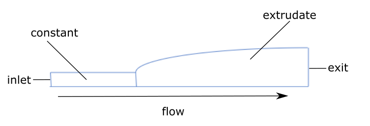
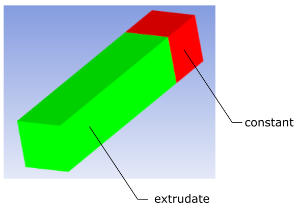
For constant section configurations, the Simple Inverse Extrusion Wizard requires a topology which includes specific zones and boundaries. Required zones are a die channel made of a constant section, as well as an extrudate. Required boundaries include an inlet, an outlet, one or several walls, free surface(s), and possibly one or several symmetry planes, as suggested in the following figures:

As such, when using the wizard, zones are expected to have specific names:
| Role in the Wizard | Recommended Zone Name | |
|---|---|---|
| Zones | constant part of the die | constant |
| extrudate | extrudate | |
| Boundary Zones | inlet | inlet |
| first symmetry plane | symmetry1 | |
| second symmetry plane | symmetry2 | |
| die walls | wall | |
| free surface | freesurface | |
| extrudate-exit | exit |
Note: In general, all boundaries containing "symm" will be considered as symmetry boundaries, all boundaries containing "wall" will be considered as wall boundaries, and all boundaries containing "freesurf" will be considered as free surface boundaries, however, a single boundary must be named "exit" for the extrudate exit, and a single boundary must be named "inlet" for the inlet condition. Symmetry boundaries are, of course, optional, and while these boundaries may or may not exist, the workspace will use them if present.
This collection of wizards is available for you to quickly set up and solve blow molding or thermoforming problem for a given mesh. The blow molding and thermoforming wizards, however, require shell geometries, and otherwise expect a particular topology, as described in Expected Topologies for the Blow Molding / Thermoforming Wizards.
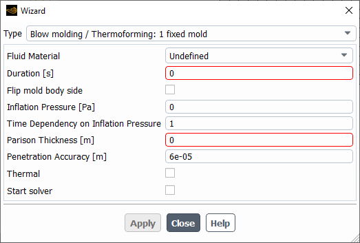
Specify a particular Type of wizard, depending on your requirements. Choices include:
Blow Molding / Thermoforming: 1 fixed mold
Blow Molding / Thermoforming: 1 mold driven by force
Blow Molding / Thermoforming: 1 mold driven by velocity
Blow Molding / Thermoforming: 2 molds driven by force
Blow Molding / Thermoforming: 2 molds driven by velocity
Specify the Fluid Material.
Specify the Duration.
Determine the orientation of the mold body.
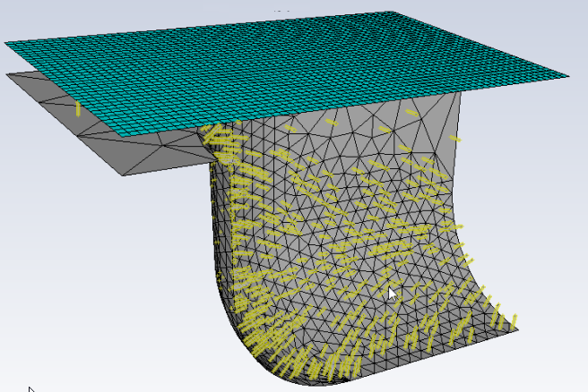
If the workspace identifies the mesh as a mold using topological names, then arrows are used in the graphics window to help you visualize the current direction of the mold body orientation. When using a single mold, use the Flip mold body side check box to change the direction of (or "flip") the mold body's orientation.
When using two molds, you can choose to use the Flip mold1 body side and/or the Flip mold2 body side check box.
In Figure 4.51: Example of Graphical Indicators of Mold Body Orientation, for instance, note that the darts point in the direction of the single mold cavity. Consequently, you can use the Flip mold body side check box to reverse the orientation of the darts so that they point into the mold body side.
When the Type is set to Blow Molding / Thermoforming: 1 mold driven by force, specify the mass, maximum displacement of the mold, and the force components acting/applied on it and its initial velocity:
Specify the Mold Mass.
Specify the Mold Maximum Displacement
Specify the x-, y-, and z-components of the translational force acting/applied on the mold (Mold Translation Force - Fx, Mold Translation Force - Fy, and Mold Translation Force - Fz).
Specify the x-, y-, and z-components of the mold's initial velocity (Mold Initial Velocity - Vx, Mold Initial Velocity - Vy, and Mold Initial Velocity - Vz).
When the Type is set to Blow Molding / Thermoforming: 1 mold driven by velocity, specify the velocity components of the mold.
Specify the x-, y-, and z-components of the mold's velocity (Mold Velocity - Vx, Mold Velocity - Vy, and Mold Velocity - Vz) as either a constant or an expression.
When the Type is set to Blow Molding / Thermoforming: 2 molds driven by force set the mass, maximum displacement of the molds, and force components acting /applied on them, and their initial velocities:
Specify whether the first mold is fixed or not (Mold1 fixed).
Specify the mass of the first mold (Mold1 Mass).
Specify the maximum displacement of the first mold (Mold1 Maximum Displacement).
Specify the x-, y-, and z-components of the translational force acting/applied on the first mold (Mold1 Translation Force - Fx, Mold1 Translation Force - Fy, and Mold1 Translation Force - Fz).
Specify the x-, y-, and z-components of the first mold's initial velocity (Mold1 Initial Velocity - Vx, Mold1 Initial Velocity - Vy, and Mold1 Initial Velocity - Vz).
Specify whether the second mold is fixed or not (Mold2 fixed).
Specify the mass of the second mold (Mold2 Mass).
Specify the maximum displacement of the second mold (Mold2 Maximum Displacement).
Specify the x-, y-, and z-components of the translational force acting/applied on the second mold (Mold2 Translation Force - Fx, Mold2 Translation Force - Fy, and Mold2 Translation Force - Fz).
Specify the x-, y-, and z-components of the second mold's initial velocity (Mold2 Initial Velocity - Vx, Mold2 Initial Velocity - Vy, and Mold2 Initial Velocity - Vz).
When the Type is set to Blow Molding / Thermoforming: 2 molds driven by velocity, set the velocity components of the mold(s):
Specify whether the first mold is fixed or not (Mold1 fixed).
Specify the x-, y-, and z-components of the first mold's velocity (Mold1 Velocity - Vx, Mold1 Velocity - Vy, and Mold1 Velocity - Vz) as either a constant or an expression.
Specify whether the second mold is fixed or not (Mold2 fixed).
Specify the x-, y-, and z-components of the second mold's velocity (Mold2 Velocity - Vx, Mold2 Velocity - Vy, and Mold2 Velocity - Vz) as either a constant or an expression.
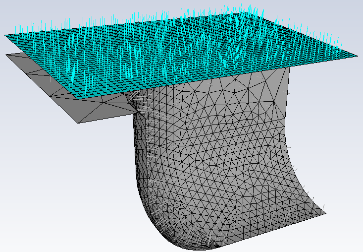
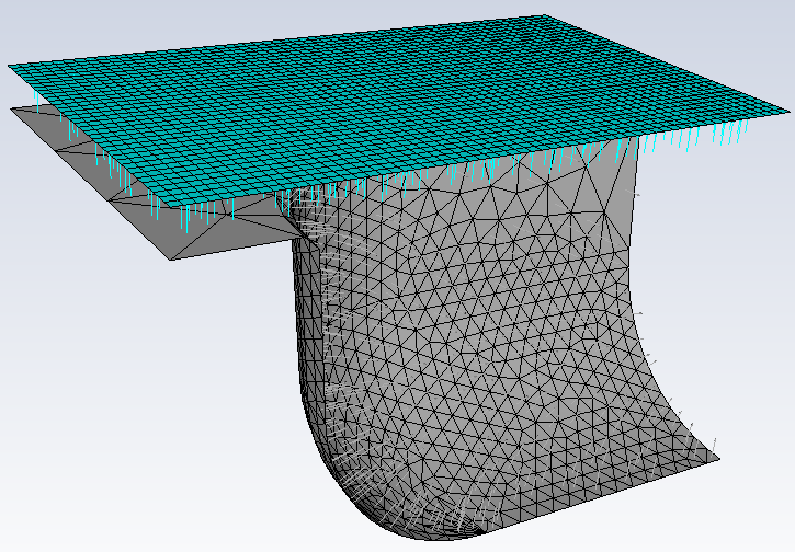
Specify the Inflation Pressure. If the workspace identifies the mesh as a parison using topological names, then arrows are used in the graphics window to help you visualize the direction of the inflation pressure.
Changing the sign of the value of the inflation pressure changes the orientation of the darts in the graphics window, and therefore the way the air pushes on the polymer sheet.Specify the Time Dependency on Inflation Pressure as either a constant or an expression.
Specify the Parison Thickness.
Specify the Penetration Accuracy.
Enable the Thermal option if temperatures are important in your simulation, in which case, you can then provide the Mold Temperature, the Parison Temperature, and the Heat Transfer Coefficient. If you selected a wizard with two molds, you can specify the Mold1 Temperature and the Mold2 Temperature.
Use the Start solver option to automatically start solving the simulation once the simulation has been set up.
If this option is enabled, once you click Apply and leave the wizard, the workspace takes your settings and sets up the blow molding/thermoforming simulation accordingly. Once the calculations are completed, you can easily proceed to analyze the results.
The Blow Molding / Thermoforming Wizards require a specific topology, depending on your simulation. As such, when using the wizard, zones are expected to have specific names:
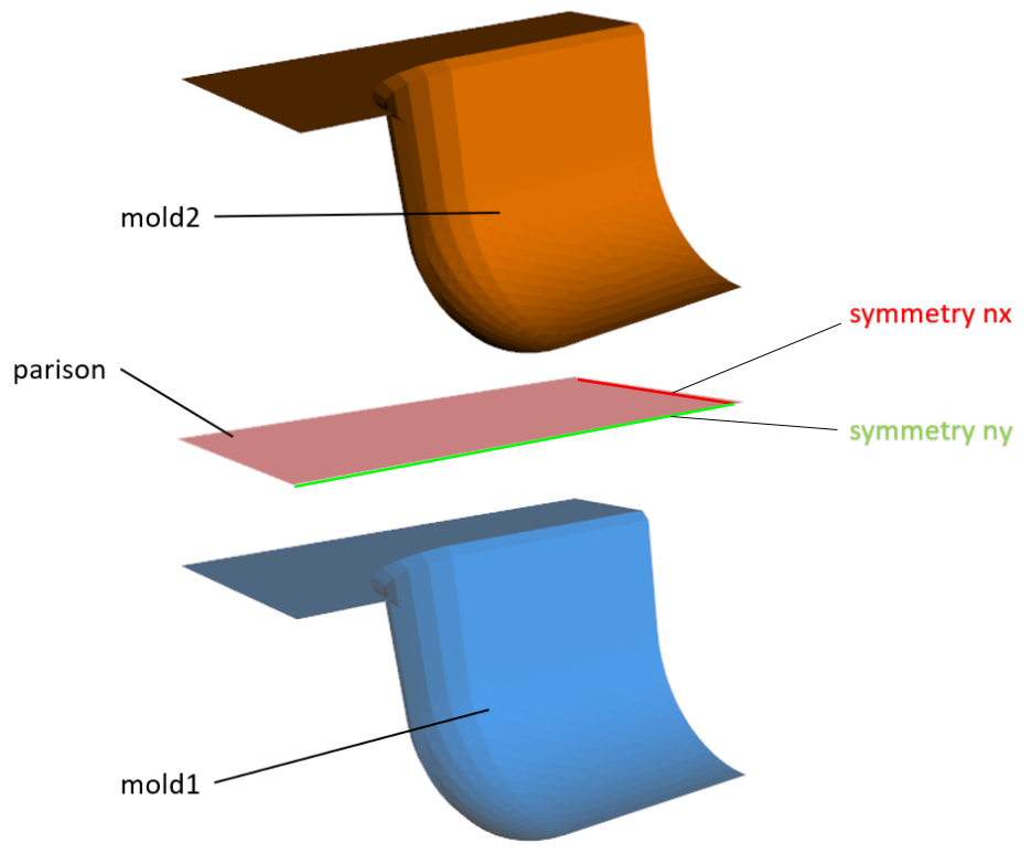
The following table summarizes the expectations and behavior for how the blow molding / thermoforming wizards manage zones for a given topology:
| 1 Fixed Mold | 1 Mold - Velocity Driven | 1 Mold - Force Driven | 2 Molds - Velocity Driven | 2 Molds - Force Driven | Original Topology Name | Modified Topology Name | |
|---|---|---|---|---|---|---|---|
| Zones | * | * | * | * | * | "fluid" or "parison" | <topology-name> included in the fluid cell zone name |
| * | * | * | <topology-name> included in the mold cell zone | ||||
| * | * | "mold1" | <topology-name> + "<fixed/moving>-mold1" | ||||
| * | * | "mold2" | <topology-name> + "<fixed/moving>-mold2" | ||||
| Boundary Zones | * | * | * | * | * | "fixed" | fixed-edges boundary condition (zero
velocity) |
| * | * | * | * | * | "free" | free-edges boundary condition (zero
force) | |
| * | * | * | * | * | "symm" and "nx" | symmetry boundary condition, with
normal = nx | |
| * | * | * | * | * | "symm" and "ny" | symmetry boundary condition, with
normal = ny | |
| * | * | * | * | * | "symm" and "nz" | symmetry boundary condition, with
normal = nz |
Note: The wizards take action when the topology name contains either "fluid" or "parison" or "mold1" or "mold2". No action is taken however if, for example, the topology name contains just "mold" or just "symm".