


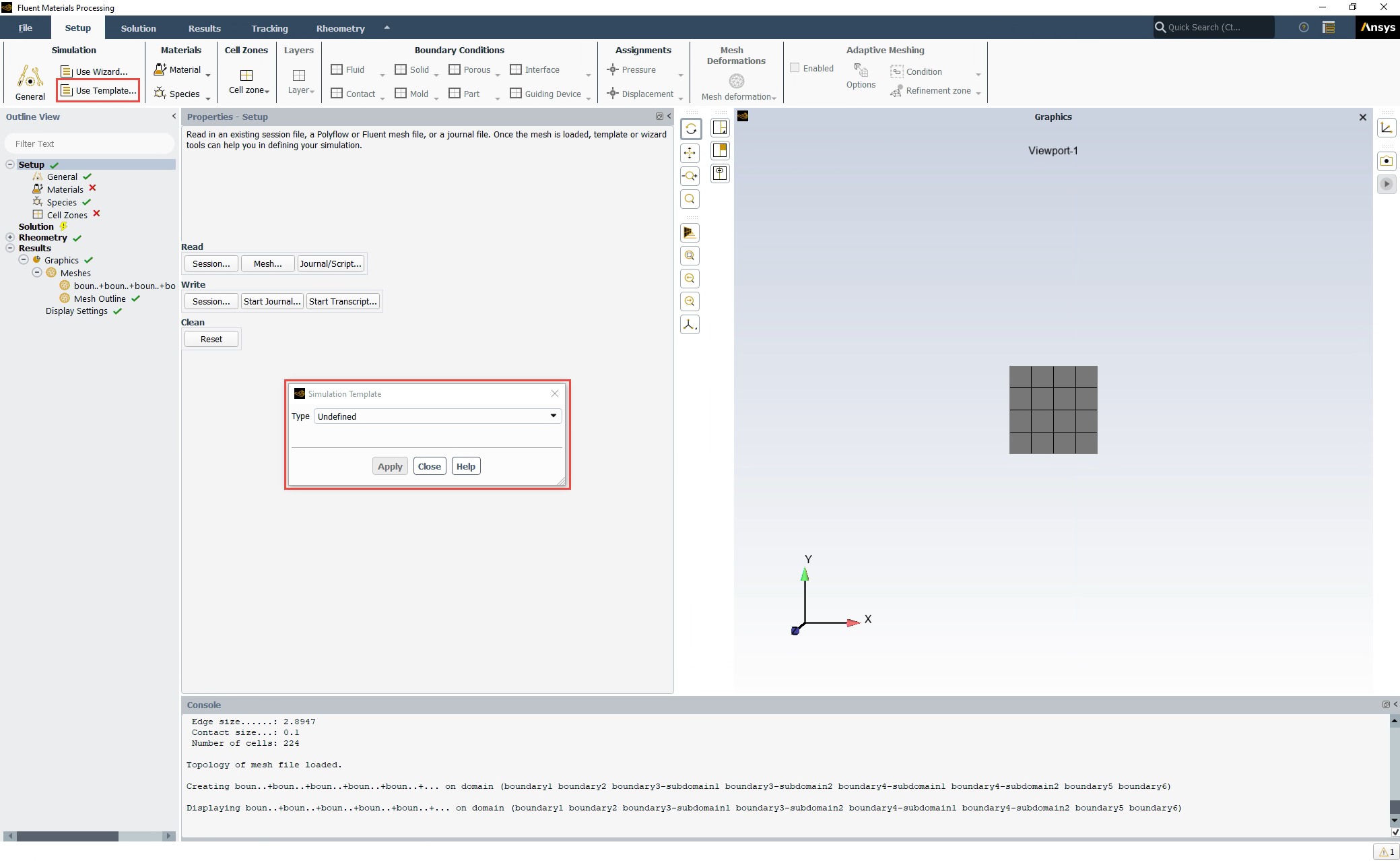
To use a simulation template in the workspace, click the Use template... button, under the Simulation category, in the Setup Ribbon. This displays the Simulation Template dialog.
The following laminar flow simulation types are available using templates:
Internal Flow (Using the Internal Flow Template) - available in 2D and 3D.
Extrusion (Using the Extrusion Template) - available in 2D and 3D.
Blow Molding & Thermoforming (Using the Blow Molding & Thermoforming Template) - available in shell only.
Pressing (Using the Pressing Template) - available in 2D and 3D.
Compounding and Mixing (Using the Compounding & Mixing Template) - available in 2D and 3D.
Film Casting (Using the Film Casting Template) - available in 2D only.
Filling (Using the Filling Template) - available in 2D and 3D.
The Internal Flow template helps you quickly set up a simple simulation of internal flow through a pipe, a die or any hollow object. With this option, several boundary conditions are already provided for you as part of the template:
inlet: an open boundary where fluid is entering the physics region.
outlet: an open boundary where fluid is exiting the physics region.
wall: a closed boundary across which fluid cannot flow into or out of the physics region.
Note: You may also want to take advantage of any symmetry in your simulation. In such cases, you can choose to add separate boundary condition(s). A symmetry boundary represents a closed boundary at a plane of symmetry across which fluid is not expected to flow.
Specify whether or not to include Thermal considerations.
Specify whether or not to include Conjugate Heat Transfer considerations.
When you have made your selections, click Apply to get started. The Outline View will be populated with elements corresponding to the choices you make in the template. The settings of each element will then have to be reviewed and completed as necessary.
For additional information on simulating these types of flows in the Fluent Materials Processing workspace, see Modeling Internal Flows.
The Extrusion template helps you quickly set up a simulation where you can investigate the extrusion of materials such as polymer, uncured rubber, molten glass, and food-related materials.
Specify the extrusion simulation Goal
Select Analyze flow within die when you want to investigate the laminar flow within just the die itself. With this option, several boundary conditions are already provided for you as part of the template:
inlet: an open boundary where fluid is entering the physics region.
outlet: an open boundary where fluid is exiting the physics region.
wall: a closed boundary across which fluid cannot flow into or out of the physics region.
Select Predict extrudate shape when you want to determine the shape of the extrudate based on the geometry of the die, material properties, and operating conditions. With this option, several objects are already provided for you as part of the template:
extrudate: the deformation of the extrudate.
free surface: a boundary that represents the outer surface of the extrudate.
extrudate exit: an open boundary where the fluid exits at the extremity of the extrudate region.
inlet: an open boundary where fluid is entering the physics region.
wall: a closed boundary across which fluid cannot flow into or out of the physics region.
Select Determine die lip shape when you want to determine the shape of the die lip corresponding to the desired cross section of the extrudate. With this option, several objects are already provided for you as part of the template:
extrudate: the deformation of the extrudate.
free surface: a boundary that represents the outer surface of the extrudate.
die deformation: the deformation of the die.
extrudate exit: an open boundary where the fluid exits at the extremity of the extrudate region.
inlet: an open boundary where fluid is entering the physics region.
wall: a closed boundary across which fluid cannot flow into or out of the physics region.
Note: In either case, you may also want to take advantage of any symmetry in your simulation. In such cases, you can choose to add separate boundary condition(s). A symmetry boundary represents a closed boundary at a plane of symmetry across which fluid is not expected to flow.
Specify the Number of Fluids. The template allows you to define coextrusion with two or more different materials: assuming that each material enters through a different inlet. When the number of fluids is greater than one, then the fluid materials must be designated as Generalized Newtonian materials.
Specify the Number of Restrictors.
Note: A restrictor is an obstacle, also called a choker, placed within the flow channel to better control the flow and to obtain the targeted flow distribution, in general to have a more uniform velocity profile at the exit of the die.
Specify whether or not to include Thermal considerations.
Specify whether or not to include Conjugate Heat Transfer considerations.
When you have made your selections, click Apply to get started. The Outline View will be populated with elements corresponding to the choices you make in the template. The settings of each element will then have to be reviewed and completed as necessary.
For additional information on simulating these types of flows in the Fluent Materials Processing workspace, see Modeling the Prediction of Extrudate Shape (Direct Extrusion) and Modeling the Determination of Die Lip Shape (Inverse Extrusion).
The Blow Molding & Thermoforming template helps you quickly set up a simulation where you can investigate the blow molding and thermoforming processes, usually for molten polymers.
Note: A shell mesh is required for this template.
Specify the Number of Fixed Molds.
Specify the Number of Moving Molds.
Specify the Number of Layers.
Specify the Duration for the simulation.
Specify whether or not to include Thermal considerations.
When you have made your selections, click Apply to get started. The Outline View will be populated with elements corresponding to the choices you make in the template. The settings of each element will then have to be reviewed and completed as necessary.
For additional information on simulating these types of flows in the Fluent Materials Processing workspace, see Modeling Blow Molding and Thermoforming.
The Pressing template helps you quickly set up a transient simulation where you can investigate the behavior of fluids (often polymer or glass) in a pressing process.
Specify the Number of Fixed Molds.
Specify the Number of Moving Molds.
Specify the Duration for the simulation.
Specify whether or not to include Thermal considerations.
Specify whether or not to include Conjugate Heat Transfer considerations.
When you have made your selections, click Apply to get started. The Outline View will be populated with elements corresponding to the choices you make in the template. The settings of each element will then have to be reviewed and completed as necessary.
For additional information on simulating these types of flows in the Fluent Materials Processing workspace, see Modeling Pressing.
The Compounding & Mixing template helps you quickly set up a transient simulation in which solid moving parts such as screw extruder(s), mixing blades, piston, etc. interact with the fluid.
Specify the Mode of compounding and mixing simulation
Select Batch Mixer when you want to perform an analysis in a closed domain.
Select Extruder when you want to perform an analysis in an open domain with inlet(s) and outlet(s).
Specify the Number of Moving Parts.
Specify the Duration for the simulation.
Specify whether or nor to include Thermal considerations.
When you have made your selections, click Apply to get started. The Outline View will be populated with elements corresponding to the choice you make in the template. The settings of each element will then have to be completed: such as the definition of the initial location and the motion of each moving part, the flow rate, etc.
For additional information on simulating these types of flows in the Fluent Materials Processing workspace, see Modeling Compounding and Mixing.
For more details, see Flows with Internal Moving Parts in the Polyflow User's Guide.
The Film Casting template helps you quickly set up a simulation where you can investigate polymer film casting.
Specify the Number of Layers.
Specify whether or not to include Thermal considerations.
When you have made your selections, click Apply to get started. The Outline View will be populated with elements corresponding to the choices you make in the template. The settings of each element will then have to be reviewed and completed as necessary.
For additional information on simulating these types of flows in the Fluent Materials Processing workspace, see Modeling Film Casting.
The Filling template helps you quickly set up a simulation where you can investigate filling processes.
Specify the Number of Inlets.
Specify the Number of Vents.
Specify the Duration for the simulation.
Specify whether or not to include Thermal considerations.
When you have made your selections, click Apply to get started. The Outline View will be populated with elements corresponding to the choices you make in the template. The settings of each element will then have to be reviewed and completed as necessary.
For additional information on simulating these types of flows in the Fluent Materials Processing workspace, see Modeling Filling.