


Use the Describe Overset Features task to add additional overset meshing-specific tasks to the workflow. Two common types of meshes are available when using overset meshing: collar meshes and component meshes.
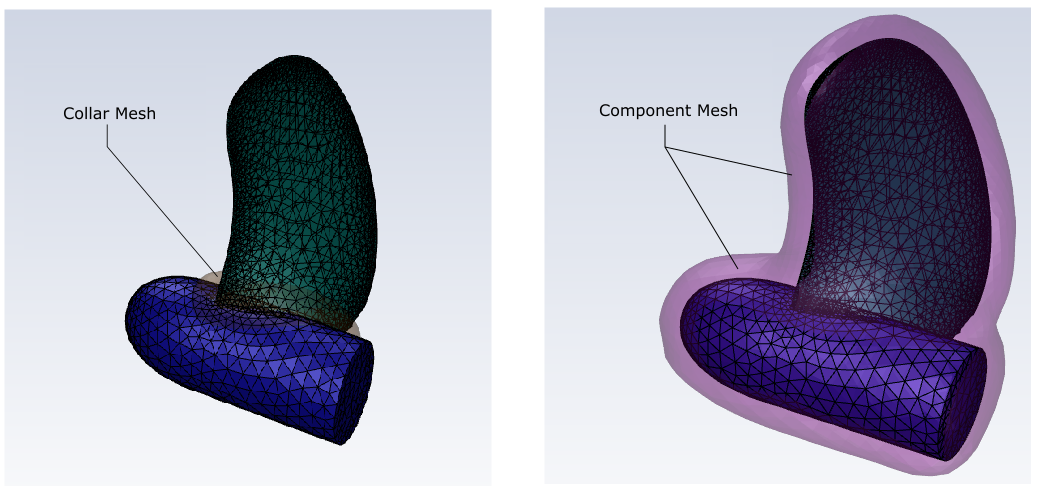
A collar mesh is a one that surrounds an intersecting point of a geometry. To add a collar mesh to your overset mesh, select Yes for the Do you want to add a collar mesh? prompt. This will add a Create Collar Mesh to your workflow. See Creating Collar Meshes for more information.
A component mesh is a one that closely surrounds a specific component of interest of a geometry. To add a component mesh to your overset mesh, select Yes for the Do you want to add a component mesh? prompt. This will add a Create Component Mesh to your workflow. See Creating Component Meshes for more information.
Note: For more information about overset meshes and using them with Fluent in solution mode, see Overset Meshes
Use this task to create a collar mesh for use with overset meshing in your workflow.
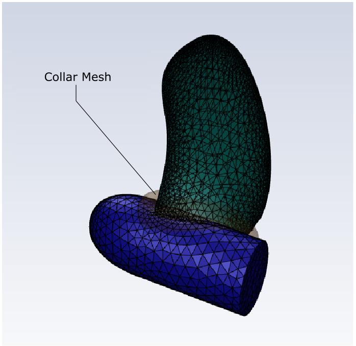
A collar mesh is often necessary when you have two intersecting bodies and you are considering overset meshing.
Specify a Name for the collar mesh, or use the default name (
collar-mesh-1).Choose the Creation Method that you will use to create the collar mesh.
Use the Intersected Objects option to create the collar mesh based on two selected intersecting bodies.
Use the Intersected Zones option to create the collar mesh based on two intersecting zones, for example, if you have one zone per face or if you use named selections in SpaceClaim to create separate zones.
Use the Edge Based Collar option to create the collar mesh using selected edges.
Use the Existing option if you have an existing object that can represent the collar mesh that already is part of your imported geometry.
Specify a value for the Max Cell Size.
For Fill With, choose the type of mesh cell to use to fill the collar mesh. Available options are tetrahedral, hexcore, poly, or poly-hexcore.
Depending on your choice of Creation Method, make an appropriate selection from the list.
Choose whether to Select By the object, label, or zone name in the list below.
Select items in the list, or use the Filter Text option in the drop-down to provide text and/or regular expressions in filtering the list (for example, using *, ?, and []). You can also choose the Use Wildcard option in the drop-down to provide wildcard expressions in filtering the list. When you use either
?or*in your expression, the matching list item(s) are automatically selected in the list. Use^,|, and&in your expression to indicate boolean operations for NOT, OR, and AND, respectively. See Filtering Lists and Using Wildcards for more information.If you have selected Intersected Objects or Edge based Collar as the Creation Method, you can specify a value for the Total Thickness that you want to use as the thickness of the collar mesh. By default, this value corresponds to four times the value of the Max Cell Size.
Use the Define Location Using field to choose how you want to assign the location of the offset collar mesh. You can choose Automatic to have the system determine the best place for the collar mesh based on the intersected bodies or zones, or you can choose to use distinct Numerical Inputs for X, Y, and Z to have more control over the collar mesh location.
Note: When creating the collar mesh, you should only use the Automatic option to preview the location of the collar mesh, but you should use the Numerical Inputs option to define the actual location.
Click Create Collar Mesh. The collar mesh will appear in the graphics window.
If you need to make adjustments to any of your settings in this task, click Revert and Edit, make your changes and click Update, or click Cancel to cancel your changes.
Use this task to create a component mesh for use with overset meshing in your workflow.
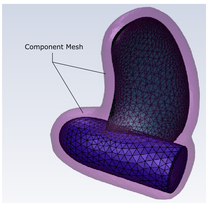
A component mesh is often necessary when you want to have a localized mesh around one or more specific portions of your geometry while considering overset meshing.
Specify a Name for the component mesh, or use the default name (
component-mesh-1).Choose the Creation Method that you will use to create the component mesh.
Use the Overset Offset Surface option to create the component mesh based on a surface that is offset from one or more selected bodies or zones.
Use the Background Box option to create the component mesh using a bounding box around the imported geometry that represents the background (for example, an enclosing box around a fan blade assembly, representing the area around the fan geometry).
Use the Existing option if you have an existing object that can represent the component mesh that already is part of your imported geometry.
Specify a value for the Max Cell Size.
For Fill With, choose the type of mesh cell to use to fill the component mesh. Available options are tetrahedral, hexcore, poly, or poly-hexcore.
Choose whether to Select By the object, label, or zone name in the list below.
Select items in the list, or use the Filter Text option in the drop-down to provide text and/or regular expressions in filtering the list (for example, using *, ?, and []). You can also choose the Use Wildcard option in the drop-down to provide wildcard expressions in filtering the list. When you use either
?or*in your expression, the matching list item(s) are automatically selected in the list. Use^,|, and&in your expression to indicate boolean operations for NOT, OR, and AND, respectively. See Filtering Lists and Using Wildcards for more information.When the Creation Method is set to Overset Offset Surface, under Offset Properties, you can also specify a value for the Total Thickness that you want to use as the thickness of the component mesh.
When the Creation Method is set to Background Box, under Box Parameters, additional settings are required.
When you select Ratio relative to geometry size, the Box Parameters hold the minimum and maximum extension ratios for the X, Y, and Z dimensions. By default, they are set to extend the dimensions of a bounding box around your selected object(s) or zone(s) out by a factor equivalent to the total singular length of the geometry in the X, Y, and Z directions. You can change the values according to your needs, and the display in the graphics window will change accordingly.
When you select Directly specify coordinates, the Box Parameters hold the minimum and maximum extension distance for the X, Y, and Z dimensions. By default, they are set to values that correspond to the extension ratios, but you can set them to more suitable values as required, and the display in the graphics window will change accordingly.
Click Create Component Mesh. The component mesh will appear in the graphics window.
If you need to make adjustments to any of your settings in this task, click Revert and Edit, make your changes and click Update, or click Cancel to cancel your changes.