


For most fluid regions, the boundary layer flow along the walls of the geometry is best captured using specialized boundary layer elements within the volume mesh (also called prisms or inflation layers). Prism elements are generated on the walls of the geometry that face the fluid region (typically referred to as "wetted" walls). You can use the Add Boundary Layers task to assign different regions to have their own boundary layer controls. This task can be added to the workflow as many times as you require. When a boundary layer is assigned to a region, all face zones associated with that region will be assigned those settings. Any zone-specific settings (except the number of layers) defined in the Prisms dialog are respected. For more information about prisms, see Generating Prisms and Growth Options for Zone-Specific Prisms and Prism Meshing Options for Scoped Prisms.
For the Add Boundary Layers? field, select yes if your model requires you to locate and address any boundary layers using the following steps. Otherwise, if your model does not require you to have boundary layers, keep the default of no, click Update and proceed to the next task.
Specify a Name for the boundary layer, or use the default value. Note that the default name is dependent on the value of the Offset Method Type.
Choose an Offset Method Type. The offset method that you choose determines how the mesh cells closest to the boundary are generated. See Offset Distances for more information. Choices include:
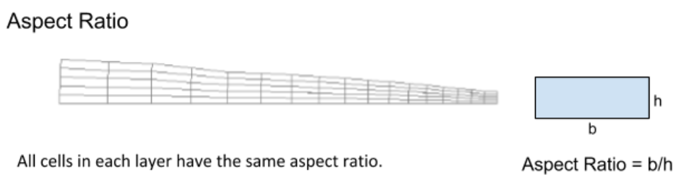
aspect-ratio: allows you to control the aspect ratio of the boundary layer cells (or prism cells) that are extruded from the base boundary zone. The aspect ratio is defined as the ratio of the prism base length to the prism layer height.
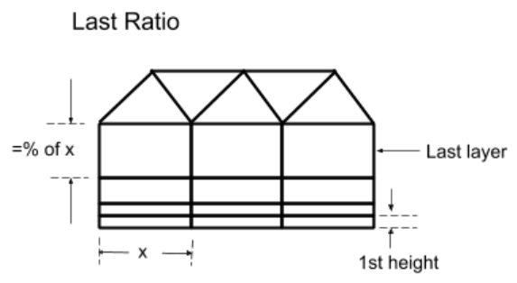
last-ratio: allows you to control the aspect ratio of the boundary layer cells (or prism cells) that are extruded from the base boundary zone. You can specify First Height for the first prism layer.
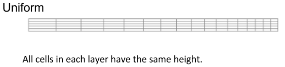
uniform: allows you to generate every new node (child) to be initially the same distance away from its parent node (that is, the corresponding node on the previous layer, from which the direction vector is pointing).
If the Offset Method Type is set to last-ratio, specify the Transition Ratio. This value determines the ratio of the height of the last layer in the inflation and the first cell in the volume fill.
If the Offset Method Type is set to aspect-ratio, specify the First Aspect Ratio. You can control the heights of the inflation layers by defining the aspect ratio of the inflations that are extruded from the inflation base. The aspect ratio is defined as the ratio of the local inflation base size to the inflation layer height. The value for the First Aspect Ratio allows you to specify the first aspect ratio to be used.
In addition, you can specify the First Height. This value is the height of the first layer of cells in the boundary layer.
If the Offset Method Type is not set to last-ratio, provide the Growth Rate. This value determines the relative thickness of adjacent inflation layers. As you move away from the face to which the inflation control is applied, each successive layer is approximately one growth rate factor thicker than the previous one.
Specify the Number of Layers. This value determines the maximum number of boundary layers to be created in the mesh.
For the Add in field, specify what regions you would like to add the boundary layers.
Use the fluid-regions option to add the boundary layer to just the fluid regions.
Use the named-regions option to select from a list of available named region(s) in your simulation.
For the Post Improvement Method option, specify how you would like to improve the boundary layer after its been generated in the specified area(s): as a Continuous or a staggered Stair Step boundary layer.
The Continuous method does not support baffles, and you should avoid using it if your specified region(s) contains any such structures; you should instead use the Stair Step method, where baffles are supported, however, they cannot be split.
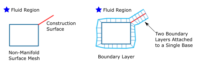
Note: Since continuous boundary layers are only applicable for manifold regions, the task will not create boundary layers if it detects a non-manifold surface mesh (for example, when two boundary layers are attached to a single base, such as when considering a construction surface around a non-manifold surface mesh).
See Prism Meshing Options for Scoped Prisms for more information.
For the Grow on field, specify where you would like to develop the boundary layers.
Use the only-walls option to grow the boundary layer along just wall surfaces.
Use the all-zones option to grow the boundary layer along all surfaces or zones.
Use the selected-zones option to select from a list of available Zones along which to grow the boundary layer. This option is available when Add In is set to named-regions and when Stair Step is selected as the Post Improvement Method.
Use the selected-labels option to select from a list of available Labels along which to grow the boundary layer.
For the selected-zones and selected-labels options, select items in the list, or use the Filter Text option in the drop-down to provide text and/or regular expressions in filtering the list (for example, using *, ?, and []). You can also choose the Use Wildcard option in the drop-down to provide wildcard expressions in filtering the list. When you use either
?or*in your expression, the matching list item(s) are automatically selected in the list. Use^,|, and&in your expression to indicate boolean operations for NOT, OR, and AND, respectively. See Filtering Lists and Using Wildcards for more information.
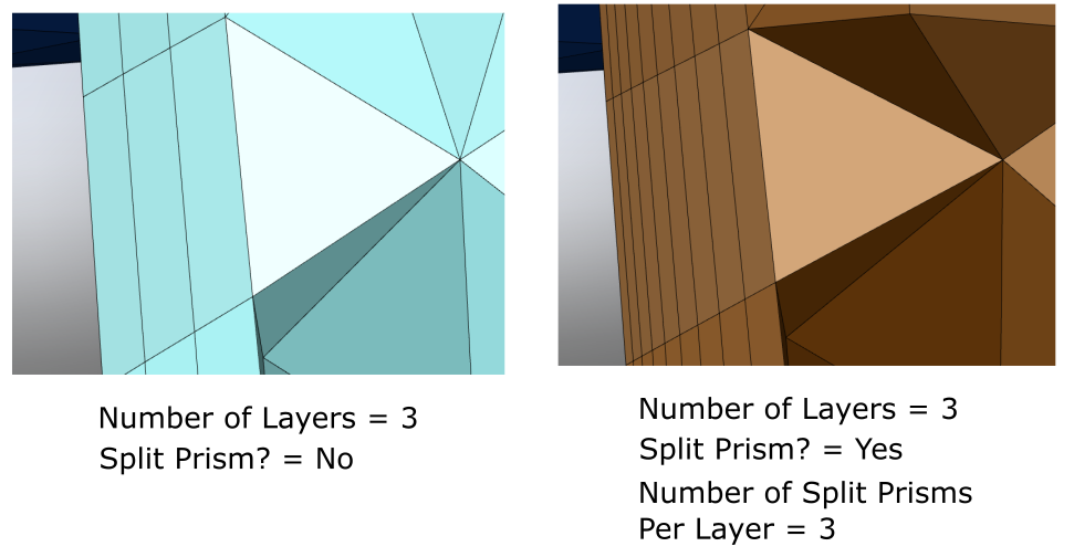
For the Split Prisms? field, choose whether or not to provide split prism layers within the individual boundary layers. This option is not available when the Offset Method Type is set to last-ratio.
When set to Yes, specify the Number of Split Prisms Per Layer. This can provide additional refinement in the flow volume's boundary layer.
For instance, for a boundary layer definition where the Number of Layers is set to 3, then, when setting Split Prisms? to Yes, and setting the Number of Split Prisms Per Layer to 3 will, once the volume mesh is generated, provide three layers of split prisms for each of the defined layers, for a total of nine layers along the boundary.
Note:When using the Stair Step method, if you choose to split prisms (setting Split Prisms? to Yes), you must also ensure that the Number of Layers is the same for all stair-step tasks, however, the Number of Split Prisms Per Layer can be different. There are no restrictions on the Number of Layers when you choose not to split prisms.
When using the Continuous method (where generally, "continuous" means that prisms have the same number of layers from all zones), if you choose to split prisms (setting Split Prisms? to Yes),the Number of Layers can only be defined in the first continuous prism task. Subsequent continuous prism layer tasks can be added by setting Grow on to selected-zones where you cannot change the number of prism layers, however, you can change other parameters (such as the aspect ratio, number of splits, etc.). In other words, the first continuous layer task sets parameters for the region and any additional, subsequent prism layer tasks overwrite all parameters except for the number of layers on the selected-zones.
The "continuous" exception is from inlets and outlets when you choose to grow the prism layers along only-walls. If the first continuous task is set to only-walls, Fluent does not allow for split prisms on any additional subsequent continuous task because an inlet or outlet may have been selected for this task (where inlets and outlets do not have any layers to split because they were only-walls be begin with).
Just as you can define a broad variety of boundary layer specifications, you can also split prisms along one or more boundaries with various combinations of growth mechanisms and techniques.
(optional) Use the Draw Regions button to visually display all regions, or just the fluid region(s).
Click Add Boundary Layers to generate the appropriate boundary layers for the imported CAD geometry.
If you need to make adjustments to any of your settings in this task, click Edit, make your changes and click Update, or click Cancel to cancel your changes.