After generating a surface mesh and setting up boundary layers, the Identify Deviated Faces task is available to help you identify how the wrapped surface mesh differs from the original geometry. This task can be useful for identifying deviations in the surface mesh in, for example, geometries with sharp angles.
Specify a Name for the deviation control, or use the default value.
Use the Select By field to choose whether to select the object name or the zone name in the list below.
Select items in the list, or use the Filter Text option in the drop-down to provide text and/or regular expressions in filtering the list (for example, using *, ?, and []). You can also choose the Use Wildcard option in the drop-down to provide wildcard expressions in filtering the list. When you use either
?or*in your expression, the matching list item(s) are automatically selected in the list. Use^,|, and&in your expression to indicate boolean operations for NOT, OR, and AND, respectively. See Filtering Lists and Using Wildcards for more information.Keep the Auto Compute field enabled so that the Minimum Deviation and the Maximum Deviation are automatically calculated. Otherwise, disable it and specify your own values for the Minimum Deviation and the Maximum Deviation.
Use the Overlay with options to determine how you want the deviated faces to be displayed (with or without the Mesh or Geometry).
Use the Include Gap Cover Geometry option to determine if you want to include any gap covers (Creating Gap Covers) in the check for deviated faces. If so, the default minimum and maximum deviation range is automatically calculated.
Use the Deviation drop-down button to see visualization options for identifying any irregularities in the surface mesh.
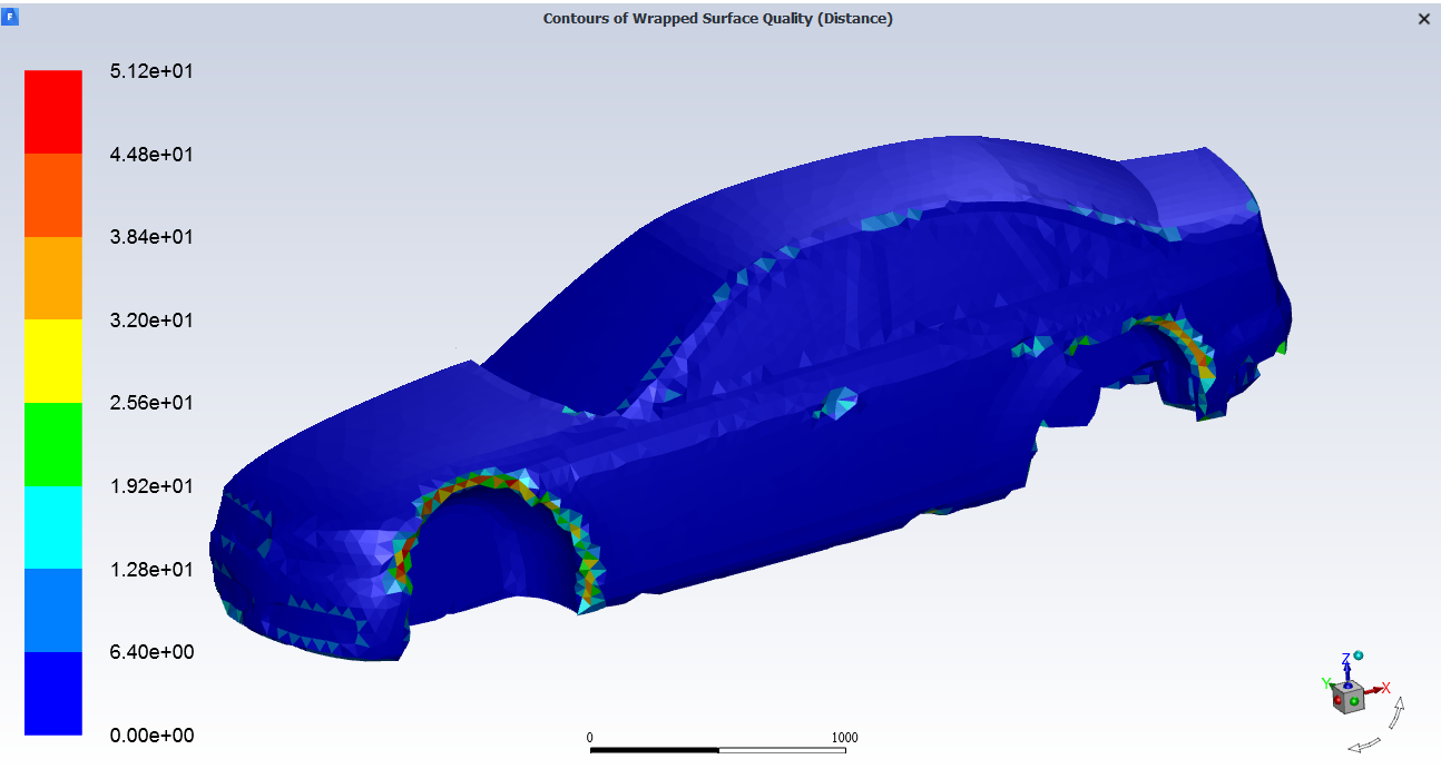
Select the Draw Contours option to see any irregular faces in the graphics window, displayed as contours of wrapped surface quality where you can identify areas of the surface mesh that do not exactly match the original geometry.
Select the Compute option to calculate values for the Minimum Deviation and the Maximum Deviation.
Once your selections are made, click Identify Deviated Faces and proceed onto the next task.
If you need to make adjustments to any of your settings in this task, click Revert and Edit, make your changes and click Update, or click Cancel to cancel your changes.