


The Generate the Volume Mesh task will perform various operations and generate the volume mesh.
If required, specify the Quality Improve Limit, or keep the default setting. This sets the threshold for when mesh quality improvements are automatically invoked that employ the orthogonal quality limit, and is recommended to be around 0.04.
Select Enable Parallel Meshing for Fluids if you would like to perform parallel volume meshing on your fluid region(s) for poly, hexcore and poly-hexcore volume fill types. When parallel is enabled, both boundary layer generation methods are parallelized: continuous and stair-step (also called "scoped").
Select Save Mesh if you would like to save the volume mesh file with your simulation.
If you would like to review and change the volume meshing technique for your region(s), you can select the Enable Region Settings option. This displays a tabular overview of the simulation's volume region(s) (including overset component regions) and their mesh settings (formerly set in the Update Region Settings task), that you can change accordingly before finally generating the volume mesh.
Choose a Volume Fill, or keep the default setting. For both fluids and solids, you can choose from tet, hexcore, poly, or poly-hexcore.
Multiple regions can be assigned a specific volume fill type all at once by selecting them in the table, right-click, and select Set Volume Fill in the context menu, then designate a volume fill type for the selected regions directly in the menu.
The Max Cell Length can be changed on a per-region basis as well, if desired.
For Advanced Options,
Use the Quality Method option to choose from different types of mesh quality controls (aspect ratio, change in size, and so on). Choices include Orthogonal (the default for the workflows) and Enhanced Orthogonal. For more information, see Quality Measure. The quality method chosen here will also be used in the Improve Volume Mesh task if you later add that task to the workflow, however, you can still choose a different quality method for that task if desired.
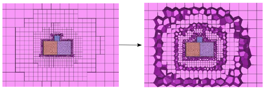
Use the Avoid 1/8 Octree Transition in Hexcore Region? option to determine whether or not you want to avoid any potential 1:8 cell transition in the hexcore or polyhexcore region of the volume mesh, replacing any abrupt change in the cell size with tetrahedral or polyhedral cells.
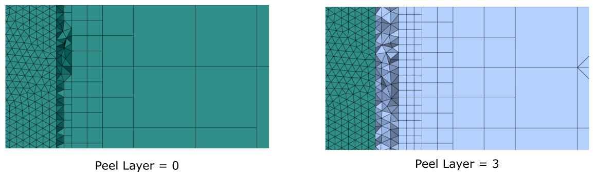
Use the Octree Peel Layers option to define the number of octree layers to be removed between the boundary and the core (see Peel Layers for details). The resulting cavity will be filled with tet cells for hexcore meshes and with poly cells for polyhexcore meshes.
Use the Use Size Field option to determine whether or not you want to use size fields when generating the volume mesh. Generating the volume mesh using size fields can require additional memory as you increase the number of processing cores. This is because the size field is replicated for each core as the size field is not properly distributed. When using size fields, you are limited by the size of the machine. When not using size fields, however, you require less memory and you can use a higher number of cores with limited RAM, leading to a faster mesh generation. When a size field is not used, then you must also make adjustments, if any, to the following fields:
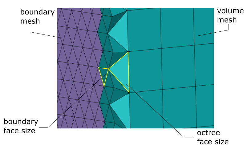
Use the Octree/Boundary Size Ratio option to set the ratio between the octree face size and the boundary face size. The default is 2.5 such that the octree mesh near the boundary is 2.5 times larger than the boundary mesh.
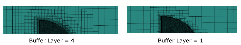
Use the Buffer Layers option to set the number of buffer layers for the octree volume mesh. If size controls have not been defined previously, then the default is 2, otherwise the default is calculated based on the maximum growth size. The buffer layers are additional layers of cells to alleviate a rapid transition from finer cells to coarser cells (see Buffer Layers for details).
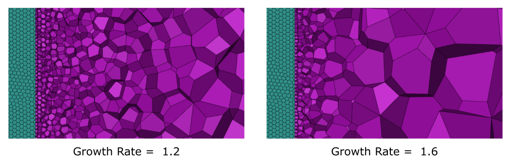
Use the Tet/Poly Growth Rate option to specify the maximum growth rate for tet and poly cells. By default, this corresponds to a growth rate of 1.2.
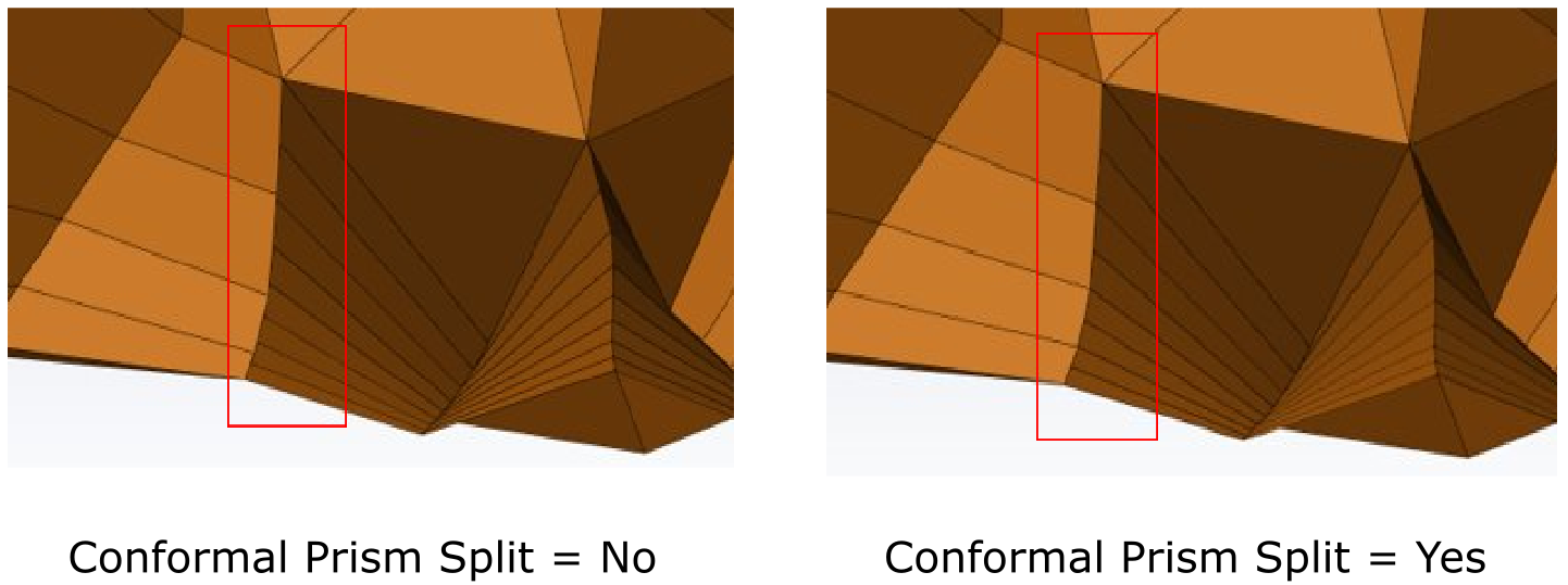
Neighboring zones with different numbers of layers will lead to conformal prism layers between them. Use the Conformal Prism Split option to determine whether you want to split the boundary layer cells conformally or not. When this option is set to Yes, the prism sides of the two zones will share nodes. This option is only available when stair-stepping is invoked. Note that adjacent regions should have an even ratio of prism layers when using this option.
The Tet-Prism Stairstep Exposed Quads? option can be used when generating a tetrahedral mesh with prism cells and is set to No by default. Selecting Yes for this option will enable stair-stepping for exposed quadrilateral faces (exposed quads) on prism cells. Stair-stepping will prevent pyramids from being created on these exposed quads, which generally would lead to poor quality in the exposed quad location.
Note: For all volume fill methods other than tetrahedral, the Tet-Prism Stairstep Exposed Quads? option is set to No and can not be changed.
Once your selection is made, click Generate the Volume Mesh and proceed onto the next task.
If you need to make adjustments to any of your settings in this task, click Revert and Edit, make your changes and click Update, or click Cancel to cancel your changes.
From this task, if you need to address any surface contact issues, you can add a Separating Contacts task to your workflow (see Separating Contacts).
Note: When using the meshing workflows, after generating the volume mesh, the default quality measure is set to Orthogonal Quality, and will be reported as such when querying the mesh quality