


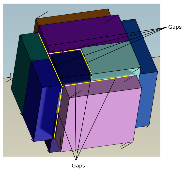
If your geometry contains any additional gaps or openings, use the Create Gap Cover task to cover such gaps before you generate the surface mesh.
Note: This task is available to add to your workflow after the Describe Geometry and Flow task, and before the Generate the Surface Mesh task. Additionally, only a single Create Gap Cover task is allowed in your workflow.
Specify a Name for the gap covering object, or keep the default value (
gap-cover-1).Select the Method to determine how the gap cover is created.
The default setting of Uniform Wrapper requires you to provide a value for the maximum width of the gap (the Max Gap Size). Alternatively, you can use the Wrapper Based on Size Field option to use the size controls defined in the Choose Mesh Control Options task.
The setting of Wrapper Based on Size Field requires you to specify the Max Gap Size Factor, or keep the default value. The size of the gap(s) that are to be closed is calculated as the product of the gap size factor and the local initial size field.
Note: If this task is located at a point in the workflow prior to the Choose Mesh Control Options task, then you can only use the Uniform Wrapper setting for the Method.
Choose whether to Select By the object, label, or zone name in the list below, of items that contain the gap that you want to cover.
Select items in the list, or use the Filter Text option in the drop-down to provide text and/or regular expressions in filtering the list (for example, using *, ?, and []). You can also choose the Use Wildcard option in the drop-down to provide wildcard expressions in filtering the list. When you use either
?or*in your expression, the matching list item(s) are automatically selected in the list. Use^,|, and&in your expression to indicate boolean operations for NOT, OR, and AND, respectively. See Filtering Lists and Using Wildcards for more information.For the Only Between Zones field, select Yes if you want to only cover gaps that exist between different boundary zones, otherwise select No to cover gaps both within and between boundary zones.
Specify a value for the Resolution Factor, or keep the default value. This allows you to control the resolution of the gap cover size based on a scaling of the Max Gap Size (or Max Gap Size Factor). It ranges from 0.0625 to 1 with a default value of 1.0). The higher the Resolution Factor, the more likely that some gaps may not be fully covered. Depending on the gap in question, lowering the Resolution Factor reduces the wrapper to sufficiently cover the gap in most cases.
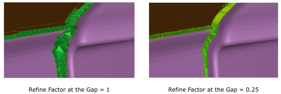
Specify a value for the Refine Factor at the Gap, or keep the default value. This setting allows you to specify the level of refinemet for the gap-cover (patch). Descreasing the value increases the refinement of the patch.
Specify a value for the Maximum Number of Island Faces, or keep the default value. This controls the maximum face count required for isolated areas (islands) to be created during gap cover generation. Any islands that have a face count smaller than this value will be removed, and only larger islands will remain. This allows you to control the maximum number of island faces your gaps may contain, reducing the number of any unwanted artifacts.
Choose whether or not to Project Nodes on Edge Features?. When this option is set to Yes, the gap covers are more accurate. Once the coarse wrap closes any gaps, this option also snaps the nodes of the wrapper onto all previously defined edge features to more closely cover the gaps. Setting this option to Yes, however, can be computationally expensive when modeling large vehicles (such as in aerospace), thus, the default is No.
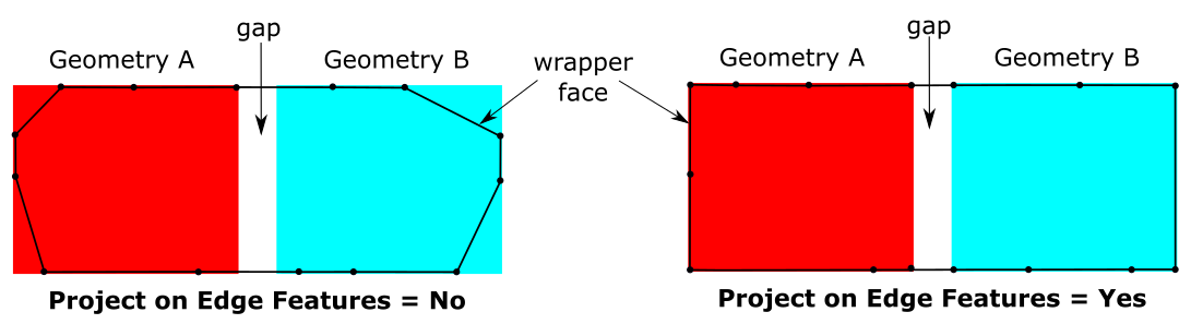
Here, when set to No, wrapper faces at the corners are not on the geometry and are incorrectly marked as a gap. When set to Yes, only wrap faces at the gap are marked.
Once your selection is made, click Create Gap Cover and proceed onto the next task.
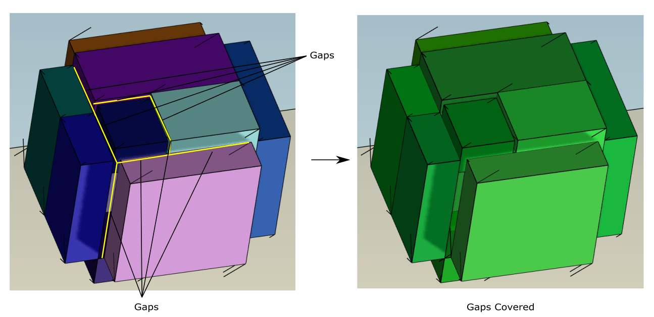
When you are done, any gaps in the geometry will be closed and you will be able to create a surface mesh.
If you need to make adjustments to any of your settings in this task, click Revert and Edit, make your changes and click Update, or click Cancel to cancel your changes.
When visualizing the results of this task using the
 icon in the
workflow,Fluent Meshing applies transparency to the objects selected for the gap cover, and
displays the subsequent gap cover group itself as a solid.
icon in the
workflow,Fluent Meshing applies transparency to the objects selected for the gap cover, and
displays the subsequent gap cover group itself as a solid.