


In complex geometries, there could be hundreds or thousands of regions ranging in various sizes, however, much of the time, you are only interested in only a few regions. Use the Identify Regions task to pinpoint specific regions in your imported geometry, such as a vehicle in an external flow simulation. Here, you are positioning specific points in the domain where certain objects of interest can be identified and classified for later use in your simulation.
In most cases, there is not a single object that defines a region. Such regions, such as most fluids and some voids, can only be identified using a specific point (also referred to as a material point).
Note: Material points can also be placed inside any additional regions that will be created as
a result of the decomposition of the main fluid region by construction surfaces (see Identifying Construction Surfaces). If material
points are not placed inside any of the decomposed regions, these regions will be
automatically identified and named according to the name of the construction surface. For
example, if you have identified a construction surface in your workflow, named
fan_mrf, any decomposed regions created from this construction
surface and which neighbors any user-defined regions, will be automatically named as
fan_mrf-1, fan_mrf-2, etc.
For the Identify Any Fluid or Void Region(s)? field, keep the default value of yes if your model requires you to specify any fluid or void regions using the following steps. Otherwise, select no, click Update and proceed to the next task.
Specify a Name for the region, or use the default name (
fluid-region-1). The default name changes depending on the assigned Region Type.For Define Location Using field, choose a method to specify the location of the region:
Select Numerical Inputs to assign specific coordinates to a particular region. You can use the Compute from Graphical Selection field to determine the region's location based on selecting a point in the graphics window. Additionally, you can use the View Exact Coordinates field to see and edit the specific X, Y, and Z coordinate values for the region's identified location.
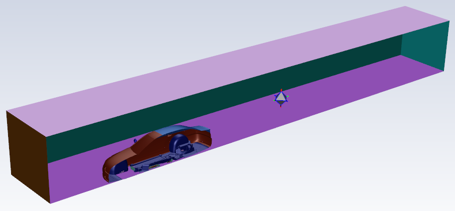
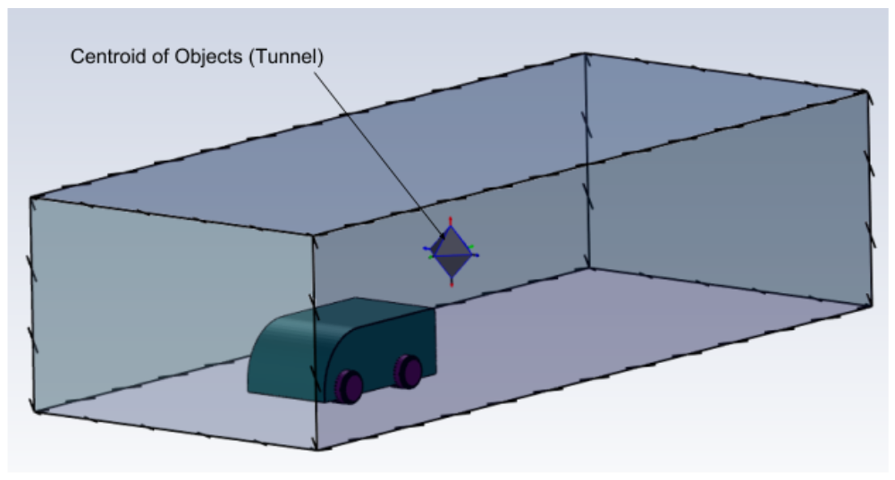
Select Centroid of Objects to calculate the position of the region based on the centroid of the selected object(s). Additionally, you can use the View Exact Coordinates field to view the specific X, Y, and Z coordinate values for the region's identified location.
Select Offset Method to calculate the region based on an offset distance relative to the centroid of a selected object/zone. Select one or more objects or zones in the corresponding Select By list, and then specify the offset distance using the Offset X, Offset Y, and Offset Z fields.
Choose a Region Type for the region (either , solid, or void).
For the Link to Construction Surface(s) field, keep the default value of no for most cases involving a singular fluid region. If, however, you mean to identify an additional fluid region that is either inside or adjacent to a construction surfaces, then set this value to yes in order to properly mesh the additional fluid region accordingly (that is, using a surface mesh).
Choose whether to Select By the object, label, or zone name in the list below.
Select items in the list, or use the Filter Text option in the drop-down to provide text and/or regular expressions in filtering the list (for example, using *, ?, and []). You can also choose the Use Wildcard option in the drop-down to provide wildcard expressions in filtering the list. When you use either
?or*in your expression, the matching list item(s) are automatically selected in the list. Use^,|, and&in your expression to indicate boolean operations for NOT, OR, and AND, respectively. See Filtering Lists and Using Wildcards for more information.Once your selections are made, click Identify Regions and proceed onto the next task.
If you need to make adjustments to any of your settings in this task, click Revert and Edit, make your changes and click Update, or click Cancel to cancel your changes.
Note: If you have previously defined regions based on specific meshing objects that you subsequently remove or rename (for example, in the Import CAD and Part Management task), you may need to revert this task in order to refresh the list of meshing objects available for your region definition. Fluent will prompt you if the list must be refreshed.
When visualizing the results of this workflow task in the graphics window (using the
 icon), Fluent Meshing applies
transparency to the fluid region(s).
icon), Fluent Meshing applies
transparency to the fluid region(s).