If your geometry contains some regions where porous media is present and you need to simulate flow through those porous regions, you can use the Create Porous Regions task to define portions of your geometry that will exhibit porous behavior in the flow field.
Simulating the pressure drop of the fluid passing through a porous media requires a separate region. This separate porous region requires a very coarse and structured mesh. The Create Porous Regions task can be used to generate such a mesh, which is used for rectangular-shaped regions.
For the Creation Method, you can choose from the following:
Select Text file to read in a text file containing the details of the porous region.
Specify a Name for the porous region, or use the default name (
porous-region)For the File Name, specify the location and name of the text file containing the definition of the porous region.
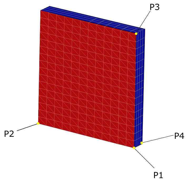
The format of the file should contain information related to the porous zone, such as the name, the coordinates of the corner points of the porous region (P1, P2, P3, and P4, described below), the cell size for each, as well as the buffer size and/or ratio: For example:
(
(name "my_porous_region")
(p1 (-10 -5 -5))
(p2 (-10 5 5))
(p3 (0 -5 -5))
(p4 (-10 -5 5))
(size-p1-p2 4)
(size-p1-p3 4)
(size-p1-p4 4)
(buffer-size-ratio 0.05)
)
Once you have selected a file, click Create Porous Regions and proceed onto the next task. The named cell zone for the porous region will be created as a child of the task. Fluent will also create a geometry object for all triangulated bounding faces.
If you need to make adjustments to any of your settings in this task, click Revert and Edit, make your changes and click Update, or click Cancel to cancel your changes.
.
Select Direct coordinates to directly enter the location and the dimensions of the porous region.
Specify a Name for the porous region, or use the default name (
porous-region).Choose whether the Specify location by field is set to Node Selection or Position Selection.
Use the right mouse button to select four points in the graphics window to define the porous region (P1, P2, P3, and P4). Their coordinates will be listed in the table in the task.
Specify a value for:
Either the Cell Size Between P1 and P2 or the Number of Cells.
Either the Cell Size Between P1 and P3 or the Number of Cells.
Either the Cell Size Between P1 and P4 or the Number of Cells.
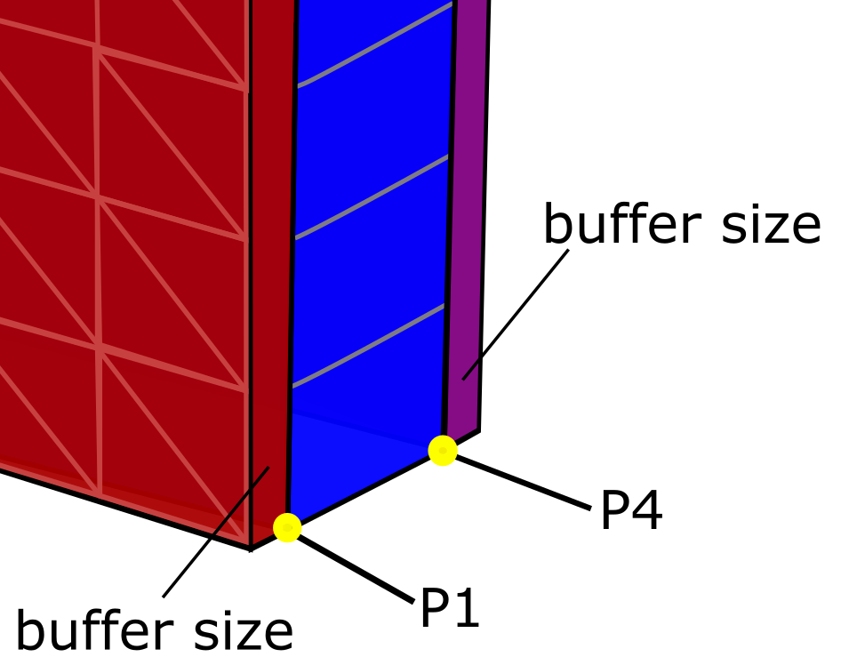
Specify a value for the Buffer Size Ratio along with the Buffer Size. There are two advantages for having a buffer zone:
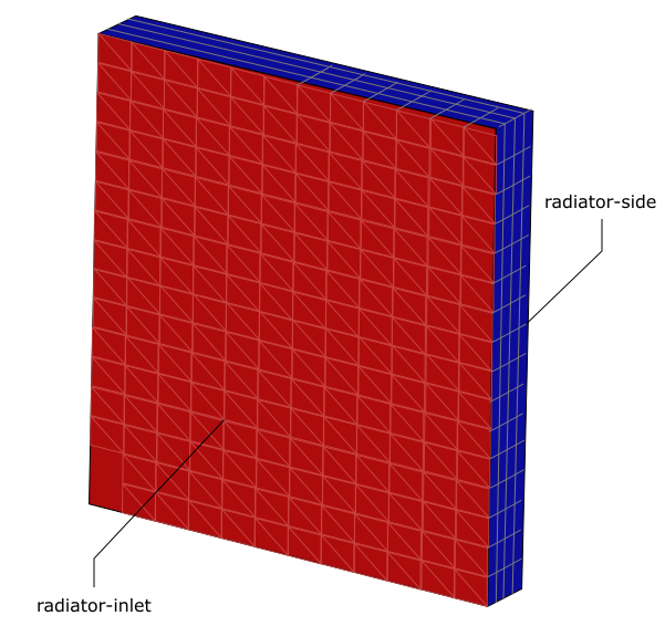
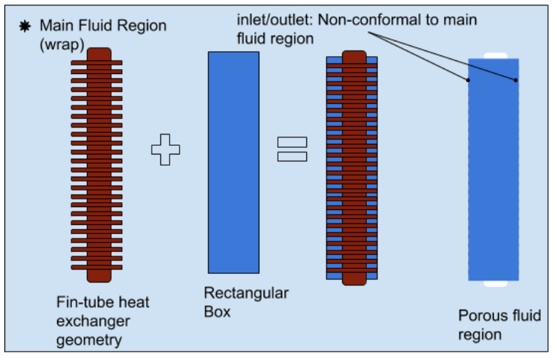
The wrapper will not detect the inlet or outlet of the core, which will avoid zone recovery issues, making for a much cleaner rezoning of the wrapper surfaces.
The macro-based heat exchanger model in the Fluent solver does not allow mesh interfaces at the inlet/outlet of the core. With the buffer layer, the inlet and outlet are conformal, and the buffer can be very thin (for example, 1 to 2 mm).
Once your selections are made, click Create Porous Regions and proceed onto the next task. The final cell zone for the porous region will be created. Fluent will also create a geometry object for all triangulated bounding faces.
If you need to make adjustments to any of your settings in this task, click Revert and Edit, make your changes and click Update, or click Cancel to cancel your changes.
Select Nonrectangular to provide information for a porous region that is not rectangular in shape.
Specify a Name for the porous region, or use the default name (
porous-region).Specify a value for the Mesh Size of the porous region, or use the default value of 8 millimeters.
Specify a value for the Thickness of the porous region, or use the default value of 8 millimeters.
Specify the Number of Layers, or divisions, along the thickness of the porous region, or use the default value of 3 layers.
Specify a value for the Feature Extraction Angle field, or use the default value of 40 degrees, for the angle at which features will be extracted for the porous region.
Specify a value for the Buffer Size for the porous region, or use the default value of 8 millimeters (see Figure 4.30: The Buffer Size for a Porous Region).
Choose whether to Select By the object, label, or zone name in the list below.
Select items in the list, or use the Filter Text option in the drop-down to provide text and/or regular expressions in filtering the list (for example, using *, ?, and []). You can also choose the Use Wildcard option in the drop-down to provide wildcard expressions in filtering the list. When you use either
?or*in your expression, the matching list item(s) are automatically selected in the list. Use^,|, and&in your expression to indicate boolean operations for NOT, OR, and AND, respectively. See Filtering Lists and Using Wildcards for more information.Use the Flip option to flip the orientation of the clipping plane to suit your requirements.