Once you have defined all of your objects in the Import Geometry and Part Management task, it's always recommended to make sure that there are no large parts missing and that all the parts fit together well. For instance, an imported car geometry may be missing a large part (such as a door), resulting in a large hole and causing potential flow leakage into the cabin. There may also be potential imperfections in the geometry (for example, missing bolts, missing sealants, etc.), resulting in other, medium sized holes. These holes may be larger than any of your initial local size controls, resulting in leaks that need to be closed.
Any missing, misaligned parts, or small imperfections will lead to leakages that need to be identified and closed using this task.
For the Would you like to close any leakages for your region(s)? field, select yes if your model requires you to locate and address any leakage issues using the following steps. Otherwise, if your model does not have any leakage issues to address, keep the default of no, click Update and proceed to the next task.
Specify a Name for the leakage threshold control, or use the default name (
leakage-1).Use the Select By field to indicate how your regions will be displayed in the table. You can select object or identified region (such as previously identified fluid, solid, or void regions). This can be helpful when you have a large number of regions.
Use the list to select the region that requires a leakage threshold control.
Select items in the list, or use the Filter Text option in the drop-down to provide text and/or regular expressions in filtering the list (for example, using *, ?, and []). You can also choose the Use Wildcard option in the drop-down to provide wildcard expressions in filtering the list. When you use either
?or*in your expression, the matching list item(s) are automatically selected in the list. Use^,|, and&in your expression to indicate boolean operations for NOT, OR, and AND, respectively. See Filtering Lists and Using Wildcards for more information.Specify a Maximum Leakage Size.
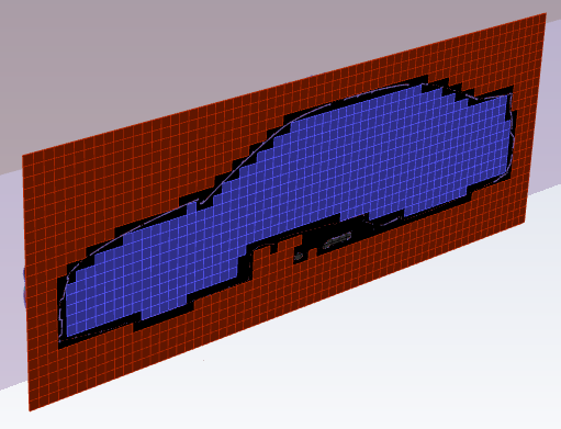
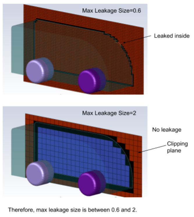
Select the Preview Leakages button to see if there are any leakages present or not. If you can see leakages occurring between regions, adjust the Maximum Leakage Size and click the Preview Leakages button again to reconstruct the generalized mesh. Repeat as needed until all leaks have been resolved.
Use a Leakage Plane controls to assess the interior of your geometry to help you to preview and identify leakages.
Use the slider to adjust the Location accordingly to visualize any leakages.
Specify the Orientation as either in the X, Y, or Z direction.
Use the Flip option to flip the orientation of the clipping plane to suit your requirements.
Once your selections are made, click Define Leakage Threshold and proceed onto the next task.
If you need to make adjustments to any of your settings in this task, click Revert and Edit, make your changes and click Update, or click Cancel to cancel your changes.
When visualizing the results of this workflow task in the graphics window (using the
 icon), Fluent Meshing only displays the
object(s) selected for the leakage threshold.
icon), Fluent Meshing only displays the
object(s) selected for the leakage threshold.