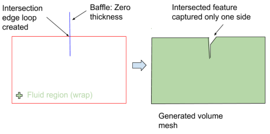
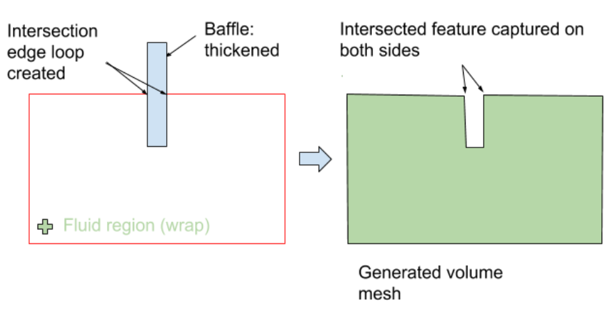
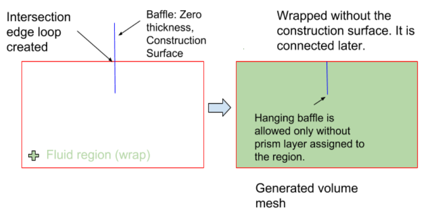
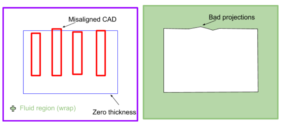
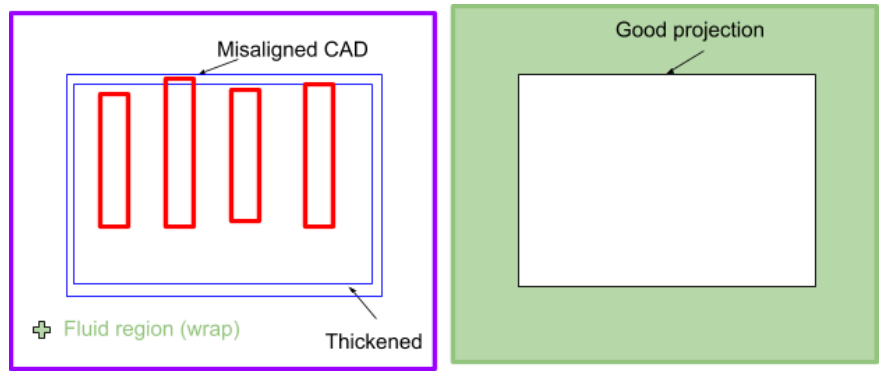
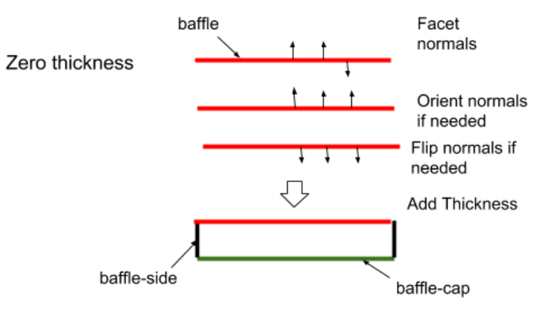
Some portions of an imported geometry may not have a thickness (such as a baffle, or other interior wall, for instance), and may be important or relevant to your simulation. A more refined surface mesh can be generated if all important and relevant aspects of the geometry have a certain thickness. Not all portions of a geometry require a thickness. However, if it has no thickness, and is important for your simulation, and contains an adequate number of quality geometry facets, then you can use the Add Thickness task to define a thickness to that portion of the geometry. The geometry is thickened in the normal direction of the facets. You may want to reverse the facet normal direction (see Manipulating Boundary Zones) before applying this operation.
Specify a Name for the zero thickness geometry, or use the default name (
face_group).Choose whether to Select By the object, label, or zone name in the list below.
Select items in the list, or use the Filter Text option in the drop-down to provide text and/or regular expressions in filtering the list (for example, using *, ?, and []). You can also choose the Use Wildcard option in the drop-down to provide wildcard expressions in filtering the list. When you use either
?or*in your expression, the matching list item(s) are automatically selected in the list. Use^,|, and&in your expression to indicate boolean operations for NOT, OR, and AND, respectively. See Filtering Lists and Using Wildcards for more information.Specify the Offset Distance that you want to use as the distance for the zero thickness geometry. The geometry will be thickened by this value. Negative values are allowed to preview the opposite/flipped direction. The original face normal will be kept, but you can add thickness in either direction based on a positive or negative value.
Once your selections are made, click Add Thickness and proceed onto the next task.
If you need to make adjustments to any of your settings in this task, click Revert and Edit, make your changes and click Update, or click Cancel to cancel your changes.
When visualizing the results of this workflow task in the graphics window (using the
 icon), Fluent Meshing only displays the
object(s) selected for the zero thickness geometry.
icon), Fluent Meshing only displays the
object(s) selected for the zero thickness geometry.The following illustrations demonstrate some examples of requiring thickness: