Ansys Fluent allows you to map variables (for example, temperature, pressure) from the cell or face zones of an Ansys Fluent simulation onto locations associated with a finite element analysis (FEA) mesh. The results are written to a file for inclusion into an FEA simulation. During this process, both the original and the new mesh can be viewed simultaneously. Ansys Fluent maps the data using zeroth-order interpolation, and can write the output file in a variety of formats.
This capability is useful when solving fluid-structure interaction (FSI) problems, and allows you to perform further analysis on the solid portion of your model using FEA software. Mapping the data may be preferable to simply exporting the Ansys Fluent data file (as described in Exporting Solution Data), since the meshes used in CFD analysis are typically finer than those used in finite element analysis.
For additional information, see the following sections:
The FEA software types that are compatible with Ansys Fluent’s FSI mapping capability include ABAQUS, I-deas, ANSYS, NASTRAN, and PATRAN. For details about the kinds of files that can be read or written during this process, see Table 3.2: FEA File Extensions for FSI Mapping.
Table 3.2: FEA File Extensions for FSI Mapping
| Type | Input File | Output File |
|---|---|---|
| ABAQUS | .inp
| .inp |
| I-deas | .unv | .unv |
| ANSYS | .cdb, .neu |
.cdb |
| NASTRAN | .bdf | .bdf |
| PATRAN | .neu, .out, .pat | .out |
To begin the process of mapping Ansys Fluent data, you must first create a mesh file that can be used as the input file in the steps that follow. The resolution of the mesh should be appropriate for your eventual finite element analysis. You are free to use the method and preprocessor of your choice in the creation of this file, but the end result must correspond to one of the entries in the Input File column of Table 3.2: FEA File Extensions for FSI Mapping.
When creating the input file, note the following:
While the input file may be scaled when it is read into Ansys Fluent, the volumes or surfaces on which the data is to be mapped must otherwise be spatially coincident with their counterparts in the Ansys Fluent simulation.
Ansys Fluent can map volume and surface data only for 3D cases; data mapping is not supported for 2D cases since data mapping for edges is not supported.
The input file can be only a portion of the overall FEA model (that is, you can exclude the parts of the model on which you are not mapping Ansys Fluent data). When this is the case, note that the numbering of the nodes and elements in the input file must match the numbering of the nodes and elements in the complete file you will use for your finite element analysis.
Next, read a case file in Ansys Fluent and make sure data is available for mapping, either by running the calculation or by reading a data file.
Finally, perform the following steps to generate an output file in which the Ansys Fluent data has been mapped to the mesh of the input file:
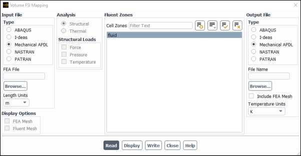
Open the Ansys Fluent dialog box that is appropriate for the zones from which the data is to be taken. If the data you are mapping is from a volume (for example, the cell zone of a solid region), open the Volume FSI Mapping dialog box using the File/FSI Mapping/Volume... ribbon tab item (Figure 3.18: The Volume FSI Mapping Dialog Box for Cell Zone Data). If instead the data is from a surface (for example, a face boundary zone), open the Surface FSI Mapping dialog box using the File/FSI Mapping/Surface... ribbon tab item (Figure 3.19: The Surface FSI Mapping Dialog Box for Face Zone Data).
 File → FSI Mapping → Volume...
or
File → FSI Mapping → Surface...
Specify the parameters of the input file and read it into Ansys Fluent.
Select the format of the input file from the Type list in the Input File group box, based on the FEA software with which it is associated. The choices include:
ABAQUS
I-deas
Mechanical APDL
NASTRAN
PATRAN
For a list of the file extensions associated with these types, see the Input File column of Table 3.2: FEA File Extensions for FSI Mapping.
Enter the name and extension (along with the folder path, if it is not in the current folder) of the input file in the FEA File text-entry box. Alternatively, you can specify it through the Select File dialog box, which is opened by clicking the button.
Specify the length units that were used in the creation of the input file by making a selection from the Length Units drop-down menu. This ensures that the input file is scaled appropriately relative to the Ansys Fluent file.
Click the button to read the input file into memory.
Important: Note that the input file will only be held in memory until the output file is written, or until the FSI mapping dialog box is closed.
Display the meshes so that you can visually verify that the input file is properly scaled and aligned with the Ansys Fluent mesh file.
Make sure that the FEA Mesh and Fluent - Mesh options are selected in the Display Options group box. Note that you can disable either of these options if you want to examine one of the meshes independently.
Click the button to display the meshes in the graphics window.
Important: For the Ansys Fluent mesh, only the zones selected in the Fluent Zones group box will be displayed—in this case, the default selections. If the default zones are not appropriate, you should redisplay the meshes after you make your zone selections in a later step.
Specify the type of data variables to be mapped.
Select either Structural or Thermal in the Analysis group box. Your selection should reflect the kind of further analysis you intend to pursue, and will determine what variables are available for mapping.
Enable the variables you want to map in the Structural Loads or Thermal Loads group box. When mapping volume data, you can enable only Temperature. When mapping surface data, you can enable Force, Pressure, and Temperature for structural analysis, or Temperature, Heat Flux, and Heat Trans Coeff for thermal analysis.
Important: Note that the Energy Equation must be enabled in the Energy dialog box if you want to map temperature for a structural analysis or any variable for a thermal analysis.
Select the zones that contain the data to be mapped in the Fluent Zones group box. You can select individual zones in the Cell Zones or Face Zones selection lists, or select all zones of a particular type in the Zone Type selection list. If you modify the default selections, you should display the meshes again, as described previously.
Important:Note that all wall zones in the Face Zones selection list are selected by default in the Surface FSI Mapping dialog box, and this includes the shadow walls created for two-sided walls. If your Ansys Fluent file contains a wall/shadow pair (for example, separating a solid zone from a fluid zone), you should make sure that only the correct wall or shadow of the pair is selected.
Inlet zones do not have heat transfer coefficient data, and so any attempts to map this combination will be ignored.
Specify the parameters of the output file and write it.
Select the format of the output file from the Type list in the Output File group box, based on the software with which you plan to perform your finite element analysis. The choices in this list are the same as those for the input file type. Note that you can select an output file type that is different from the input file type.
For details about the file extensions associated with the various types of output files, see the Output File column of Table 3.2: FEA File Extensions for FSI Mapping.
Enter the name (with the folder path, if appropriate) of the output file in the File Name text-entry box. Alternatively, you can specify it through the Select File dialog box, which is opened by clicking the button.
To include additional FEA information like node/element information in the exported output file, enable Include FEA Mesh. By default, this option is disabled and therefore, only the selected boundary condition values are exported.
When mapping temperature for a structural analysis or any variable for a thermal analysis, make a selection in the Temperature Units drop-down menu. Table 3.3: Units Associated with the Temperature Units Drop-Down List Selections shows the units for the mapped variables, depending on the Temperature Units selection.
Table 3.3: Units Associated with the Temperature Units Drop-Down List Selections
Temperature Units Selection Temperature Heat Flux Heat Transfer Coefficient K K W/ 
W/  -K
-K C °C W/ 
W/  -
°C
-
°C F °F BTU/  -hr
-hr BTU/  -hr-
°F
-hr-
°F When mapping the heat transfer coefficient for a thermal analysis, make a selection in the HTC Type drop-down menu to determine how the heat transfer coefficient
 is calculated.
- ref-temp
calculates
 using Equation 42–50, where
  is the reference temperature defined in the Reference Values Task Page. Note that this option
has the same definition as the field variable Surface Heat
Transfer Coef., as described in Alphabetical Listing of Field Variables and Their Definitions.
is the reference temperature defined in the Reference Values Task Page. Note that this option
has the same definition as the field variable Surface Heat
Transfer Coef., as described in Alphabetical Listing of Field Variables and Their Definitions.- cell-temp
calculates
 using
the general form of Equation 42–50, but
defines
using
the general form of Equation 42–50, but
defines  as
the temperature of the cell adjacent to the face.
as
the temperature of the cell adjacent to the face.- wall-func-htc
calculates
 using Equation 42–69. Note that this option has the
same definition as the field variable Wall Func. Heat Tran.
Coef., as described in Alphabetical Listing of Field Variables and Their Definitions.
using Equation 42–69. Note that this option has the
same definition as the field variable Wall Func. Heat Tran.
Coef., as described in Alphabetical Listing of Field Variables and Their Definitions.
Click Write to write an output file in which the Ansys Fluent data has been mapped to the mesh of the input file.
The input file will be released from memory when the output file is written.