


The following are examples of adapting the mesh based on different types of cell registers and one using just expressions.
If more cells are required on a boundary, they can be added using boundary adaption, which allows you to mark or refine cells in the proximity of the selected boundary zones. The ability to refine the mesh near one or more boundary zones is provided because important fluid interactions often occur in these regions (for example, the development of strong velocity gradients in the boundary layer near a wall).
An example of a mesh that can be improved with boundary adaption is shown in Figure 38.25: Mesh Before Adaption.
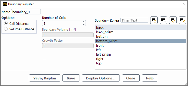
To mark cells for refinement, you can create a boundary cell register by using either the button in the Manual Mesh Adaption dialog box (as described in Boundary Layer Adaption Based on Cell Distance) or the Boundary Register dialog box (as described in Boundary and shown in Figure 38.24: Marking Boundary Cells).
Boundary adaption can be used to increase the number of cells, as shown in Figure 38.26: Mesh after Boundary Adaption. This procedure cannot increase the resolution of a curved surface. Therefore, if more cells are required on a curved surface where the shape of the surface is important, create the mesh with sufficient surface nodes before reading it into the solver.
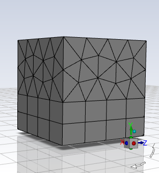
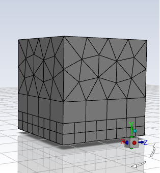
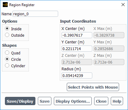
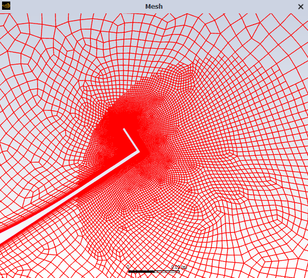
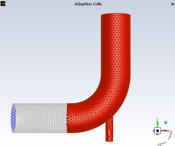
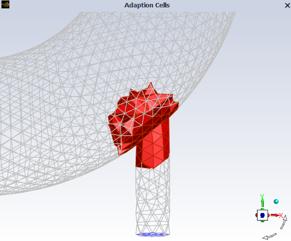
Figure 38.27: Wing Mesh Before Adaption shows a mesh that was created for solving the flow around an airfoil wing. The mesh is fine near the surface of the wing. To capture the flow separation that occurs on the surface of the wing lip, the mesh is refined after marking cells within a circular region (selected by mouse probe) surrounding the lip of the wing. Figure 38.28: Marking Cells Based on Region shows the settings that are used to mark the cells in the wake region.
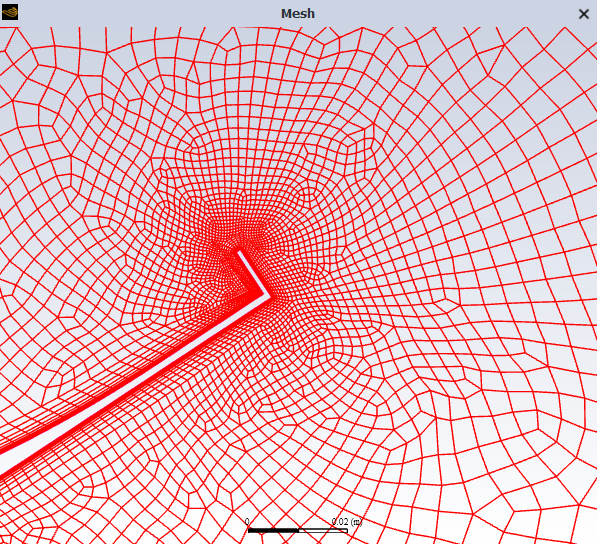
The resulting adapted mesh is shown in Figure 38.29: Wing Mesh After Region Cell Register-Based Adaption.
Direct error estimation for point-insertion adaption schemes is difficult because of the complexity of accurately estimating and modeling the error in the adapted meshes. A comprehensive mathematically rigorous theory for error estimation and convergence is not yet available for CFD simulations. Assuming that maximum error occurs in high-gradient regions, the readily available physical features of the evolving flow field may be used to drive the mesh adaption process.
When using the Scaling Option, suitable first-cut values for the Cells More Than and the Cells Less Than are 0.3 to 0.5, and 0.7 to 0.9, respectively. Smaller values will result in larger adapted regions.
Scale by Global Maximum, scales the values of
 ,
,  , or
, or  by their maximum value in the domain, therefore always returning a
problem-independent range of [0, 1] for any variable used for adaption, that is:
by their maximum value in the domain, therefore always returning a
problem-independent range of [0, 1] for any variable used for adaption, that is:
(38–1)
When using the Scale by Global Maximum option, suitable first-cut values for the Coarsening threshold and the refinement threshold are 0.2 to 0.4, and 0.5 to 0.9, respectively. Smaller values will result in larger adapted regions.
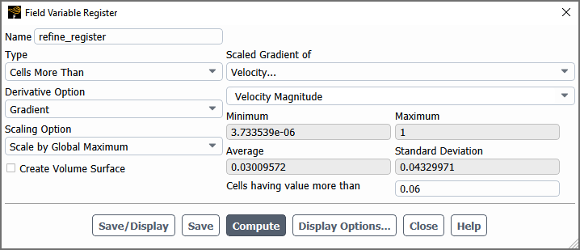
When you are using the derivative and scaling options, you can create a refinement register, like the one shown in Figure 38.30: Field Variable Refinement Register.
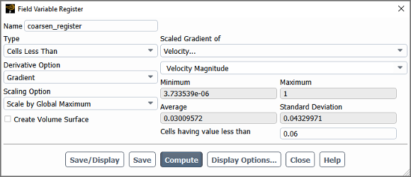
Then, using the Cells Less Than type of field variable register, you can create a coarsening cell register, as shown in Figure 38.31: Field Variable Coarsening Register.
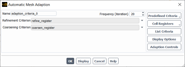
These cell registers can then be combined in the Manual Mesh Adaption or Automatic Mesh Adaption dialog box to define parameters for adaption, as shown in Figure 38.32: Controls for Refining and Coarsening the Mesh.
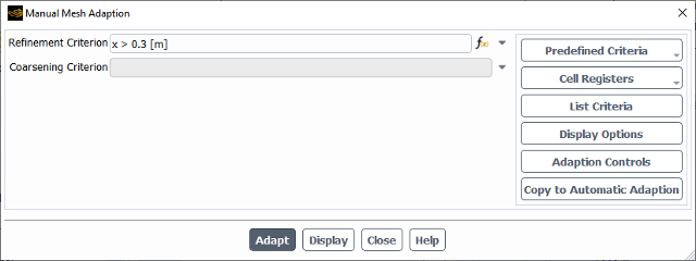
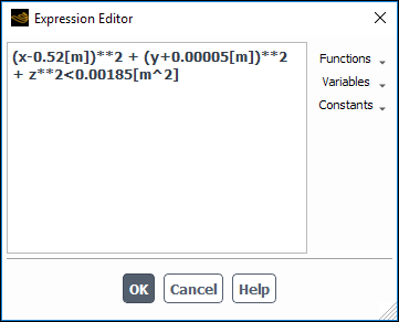
There are several ways to use expressions to perform adaption. Expressions can be used with or without cell registers to define refinement and coarsening criteria, as shown in Figure 38.33: Simple Expression Refinement Setting and Figure 38.35: Advanced Expression Refinement Setting.
Combined Boolean Operation and Variables
You can combine booleans with various postprocessing variables. For example,
AND(OR(StaticPressure<0.5[Pa], CellRefineLevel<3),
          CellVolume>1e-06[m^3])
Combined Boolean Operation and Cell Register
If you want to refine cells near an outlet where the pressure is less than
p0, you can use an expression: AND(Pressure<p0
[Pa], near_outlet_cells). Here, p0 is a constant
real value and near_outlet_cells is a boundary cell register with
specified values (refer to Boundary for
additional information on boundary cell registers).