


You can edit multiple related boundaries (zones of the same type) at the same time to simplify the setup process for Ansys Fluent cases.
Using the Multi Edit dialog box, you can edit or apply selected settings only, to a set of boundaries without opening multiple different dialog boxes. The dialog box includes colored icons to indicate which setting(s) will be applied on the selected zones.
To access the Multi Edit dialog box:
Select the boundaries that you want to edit in the Outline View tree. You can select multiple-boundaries by holding Ctrl while you left-click.
Alternatively, you can select the boundaries that you want to edit in the Adjacent Face Zones list of the Adjacency Dialog Box.
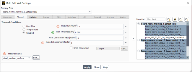
Note: One-sided (or external) walls cannot be selected together with coupled (or internal) walls for multi-editing.
Right-click the highlighted boundaries and click Multi Edit....
While Figure 7.82: The Multi Edit Wall Settings Dialog Box is only for performing a multi-edit of velocity inlets, the multi-edit functionality is available for the following boundary types:
exhaust fans
inlet vents
intake fans
mass flow inlets
mass flow outlets
outflows
outlet vents
pressure far fields
pressure inlets
pressure outlets
velocity inlets
walls
The setup for the multi-edit versions of these dialog boxes is the same as their non-multi-edit counterparts. The multi-edit functionality described in this section is consistent for all of the types.
The colored icons within the Multi Edit dialog box indicate the states of the various fields:
 indicates that the value of this setting varies between the selected boundaries.
 indicates that the displayed value will be applied to the selected boundaries when you click
.
indicates that the displayed value will be applied to the selected boundaries when you click
.You can click an icon to change its state, which would be useful if you modify multiple settings, then realize you made a mistake on one of them. To rectify the mistake, you can simply click
to remove it, indicating that the setting will not be applied when you click
.
Note: For any value entry or selection that results in changes to other fields, do not rely on just reverting the "primary field" (by clicking the
icon) to revert the other affected fields. If a field has a green check mark ( ) next to it, assume that the shown value will be applied on , regardless of
if you revert the initial change that led to the other field changes.Primary Zone lists the zone that is used as the "baseline", to which all of the other selected zones are compared. You can change which zone is selected as the primary zone by:
Select a new primary zone from the Primary Zone drop-down list.
Deselect all of the zones in the Zone list and select the desired primary zone first when re-selecting which zones to use for the multi-edit functionality.
(Multiphase simulations only) Use the Phase drop-down list to specify boundary settings for each phase. Note that you must click before selecting a new phase for the settings to be applied.
The Zone List shows the selected boundaries where the fields denoted with the
icon will be applied.You can change which boundaries are highlighted in the Zone List, allowing you to selectively apply settings to a subset of the boundaries in the list. The settings are applied to the selected (highlighted) zones when you click .
You can sort the Zone List based on adjacency or by name by clicking
 and selecting Adjacency or Name.
Note: Changes made to boundary settings using a "multi-edit" dialog box are also printed in the console and transcript (if one is being written).