


Solving for three-dimensional electrical conduction is directly analogous to the calculation of heat transfer. The potential field throughout the conductive regions is calculated based on the conservation of charge.
 | (20–107) |
where
 | (20–108) |
and  is the electrical conductivity and
  is the electrical
potential. Therefore, the governing equation for the electric field
is the Laplace equation:
is the electrical
potential. Therefore, the governing equation for the electric field
is the Laplace equation:
 | (20–109) |
The electric field potential calculation combines the following attributes:
Ohmic losses in all the conducting materials, including the electrolyte, electrodes, and current collectors.
Contact resistance at the appropriate interfaces.
Ohmic heating through conduction materials as the result of ohmic losses, and the current density throughout the domain.
For more information, see the following sections:
The electrode reactions are assumed to take place in a single step. The charge transfer reaction acts as the rate limiting step for the electrode reactions.
Oxygen is electrochemically reduced at the triple phase boundary at the cathode electrode:
 | (20–110) |
Oxygen is electrochemically re-oxidized at the triple phase boundary at the anode electrode:
 | (20–111) |
In the absence of an electrical load, the oxygen activity on both sides of the electrolyte is fixed and given by their respective chemical potentials. Under equilibrium, the electromotive force, or reversible cell voltage, is given by the Nernst equation:
 | (20–112) |
If hydrogen is present at the anode electrode, then the cell reaction becomes:
 | (20–113) |
At equilibrium, the cell voltage is given by the Nernst equation:
 | (20–114) |
where  is the open-circuit cell voltage.
The cell potential measured at equilibrium (that is, no load), is called the open circuit voltage. The open circuit voltage should be equivalent to the Nernst potential at no load, unless there is leakage across the electrolyte. When the external circuit is closed, then cell voltage drops due to polarization losses at the electrodes.
The electric field and the electrochemistry interact solely at the electrolyte interface. Ansys Fluent treats the electrolyte interface as an impermeable wall. The potential field must have a “jump" condition applied to the two sides of this wall to account for the effect of the electrochemistry. To closely couple the electrochemical behavior to the potential field calculation, you need to include all of the electrochemical effects into this jump condition. It encapsulates the voltage jump due to Nernst, the voltage reduction due to activation, the Ohmic losses due to the resistivity of the electrolyte, and are linearized for voltage reduction due to activation. This interface condition relates the potential on the anode side and the cathode side of the electrolyte and has the following form:
 | (20–115) |
where
 | (20–116) |
where  represents the ohmic overpotential of the electrolyte,
and
represents the ohmic overpotential of the electrolyte,
and  represent the activation overpotential of the anode
and the cathode.
represent the activation overpotential of the anode
and the cathode.  represent ohmic losses
in the solid conducting regions.
represent ohmic losses
in the solid conducting regions.  represents
the Nernst potential.
represents
the Nernst potential.
According to [473], the general electrochemical reaction is:
 | (20–117) |
where  is the stoichiometric coefficient of species
  ,
,  is the chemical species, and
  is the number of electrons.
Using the Bulter Volmer equation, the reaction rate (in units of kmol/(m2 S)) can be computed as:
 | (20–118) |
where  is the electric current (in units of A/m2)
generated by the electrochemical reaction,
is the electric current (in units of A/m2)
generated by the electrochemical reaction,  is the anodic symmetry factor,
  is the cathodic symmetry factor,
  is the activation potential at anode and cathode,
  is the Faraday constant,
  is the universal gas constant,
  is the temperature, and
 | (20–119) |
with  being the
exchange current density at the reference condition,
being the
exchange current density at the reference condition,  is the mole fraction
and
is the mole fraction
and  is the concentration
exponent for species
is the concentration
exponent for species  . More specifically, at the anode side, you have:
 | (20–120) |
Likewise, at the cathode side, you have:
 | (20–121) |
The exchange current density at both anode and cathode can consider the temperature dependency effect as:
 | (20–122) |
where  and
and  are rate coefficients.
Given values for  and
and  .
the full version of the Butler-Volmer equation can be solved using
the Newton method, therefore finding the activation overpotential
at the anode (
.
the full version of the Butler-Volmer equation can be solved using
the Newton method, therefore finding the activation overpotential
at the anode ( ) and the cathode
(
) and the cathode
( ).
).
For an incompressible flow, the energy equation that Ansys Fluent solves for within each computational cell is given by the following:
 | (20–123) |
where  is the volumetric source or
sink of energy and where
is the volumetric source or
sink of energy and where
 | (20–124) |
and
 | (20–125) |
In all electrically conducting zones (for example, electrodes,
current collectors, interconnects), ohmic heating,  , is added
to the energy equation as a source term. In other words,
, is added
to the energy equation as a source term. In other words,
 | (20–126) |
In addition, the energy equation needs treatment at the electrode-electrolyte interface to account for the heat generated or lost as the result of electrochemistry and the overpotentials (that is, activation overpotential and ohmic loss through the electrolyte).
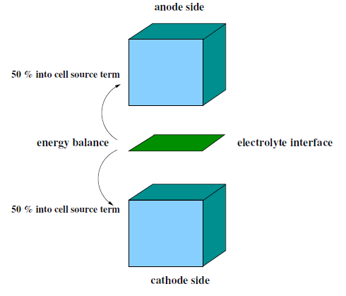
The energy balance on the electrolyte interface is computed by subtracting the electric work from the total heat generation rate due to electrochemical reactions. The electric work is calculated as the product of voltage jump and the current density. What remains is the waste heat due to irreversibilities. For hydrogen reaction, the balance would be
 | (20–127) |
where  is the heat generation (W) and
  is the product of species mass generation/consumption rate and its formation
enthalpy. For example:
is the product of species mass generation/consumption rate and its formation
enthalpy. For example:
 | (20–128) |
The source term is then added in the cell energy equation by
taking  .
.
One half of this value is applied as a source term to the energy equation of the anode computational cell adjacent to the electrolyte and the other half is applied as a source term to the energy equation for the cathode cell adjacent to the electrolyte. The equal distribution of the heat generation/destruction is purely arbitrary. Note that by using the work term, the effect from all overpotentials are taken into account.
Ohmic polarization involves ionic losses through the electrolyte, electrical resistance in the conducting porous electrodes and solid collectors. The ohmic polarization also includes the electrical resistance at the interface of the current collectors and the electrodes or the electrodes and the membrane (that is, the contact resistance).
 | (20–129) |