This section contains methods for hooking model-specific UDFs
to Ansys Fluent that have been defined using DEFINE macros found in Model-Specific DEFINE Macros, and
interpreted or compiled using methods described in Interpreting UDFs or Compiling UDFs, respectively.
For more information, see the following sections:
- 6.2.1. Hooking DEFINE_ANISOTROPIC_CONDUCTIVITY UDFs
- 6.2.2. Hooking DEFINE_CAPILLARY_PRESSURE UDFs
- 6.2.3. Hooking DEFINE_CHEM_STEP UDFs
- 6.2.4. Hooking DEFINE_CPHI UDFs
- 6.2.5. Hooking DEFINE_DIFFUSIVITY UDFs
- 6.2.6. Hooking DEFINE_DOM_DIFFUSE_REFLECTIVITY UDFs
- 6.2.7. Hooking DEFINE_DOM_SOURCE UDFs
- 6.2.8. Hooking DEFINE_DOM_SPECULAR_REFLECTIVITY UDFs
- 6.2.9. Hooking DEFINE_EC_RATE UDFs
- 6.2.10. Hooking DEFINE_EC_KINETICS_PARAMETER UDFs
- 6.2.11. Hooking DEFINE_EDC_MDOT UDFs
- 6.2.12. Hooking DEFINE_EDC_SCALES UDFs
- 6.2.13. Hooking DEFINE_ELECTROLYSIS_ECHEM_RATE UDFs
- 6.2.14. Hooking DEFINE_ELECTROLYSIS_RELATIVE_PERMEABILITY UDFs
- 6.2.15. Hooking DEFINE_EMISSIVITY_WEIGHTING_FACTOR UDFs
- 6.2.16. Hooking DEFINE_FLAMELET_PARAMETERS UDFs
- 6.2.17. Hooking DEFINE_GAP_MODEL_SOURCE UDFs
- 6.2.18. Hooking DEFINE_GEOMETRY UDFs
- 6.2.19. Hooking DEFINE_GRAY_BAND_ABS_COEFF UDFs
- 6.2.20. Hooking DEFINE_HEAT_FLUX UDFs
- 6.2.21. Hooking DEFINE_IGNITE_SOURCE UDFs
- 6.2.22. Hooking DEFINE_MASS_TR_PROPERTY UDFs
- 6.2.23. Hooking DEFINE_NET_REACTION_RATE UDFs
- 6.2.24. Hooking DEFINE_NOX_RATE UDFs
- 6.2.25. Hooking DEFINE_PERFORATED_CD UDFs
- 6.2.26. Hooking DEFINE_PDF_TABLE UDFs
- 6.2.27. Hooking DEFINE_PR_RATE UDFs
- 6.2.28. Hooking DEFINE_PRANDTL UDFs
- 6.2.29. Hooking DEFINE_PROFILE UDFs
- 6.2.30. Hooking DEFINE_PROPERTY UDFs
- 6.2.31. Hooking DEFINE_REACTING_CHANNEL_BC UDFs
- 6.2.32. Hooking DEFINE_REACTING_CHANNEL_SOLVER UDFs
- 6.2.33. Hooking DEFINE_RELAX_TO_EQUILIBRIUM UDFs
- 6.2.34. Hooking DEFINE_SBES_BF UDFs
- 6.2.35. Hooking DEFINE_SCAT_PHASE_FUNC UDFs
- 6.2.36. Hooking DEFINE_SOLAR_INTENSITY UDFs
- 6.2.37. Hooking DEFINE_SOLIDIFICATION_PARAMS UDFs
- 6.2.38. Hooking DEFINE_SOURCE UDFs
- 6.2.39. Hooking DEFINE_SOOT_MASS_RATES UDFs
- 6.2.40. Hooking DEFINE_SOOT_MOM_RATES UDFs
- 6.2.41. Hooking DEFINE_SOOT_NUCLEATION_RATES UDFs
- 6.2.42. Hooking DEFINE_SOOT_OXIDATION_RATE UDFs
- 6.2.43. Hooking DEFINE_SOOT_PRECURSOR UDFs
- 6.2.44. Hooking DEFINE_SPARK_GEOM UDFs
- 6.2.45. Hooking DEFINE_SPECIFIC_HEAT UDFs
- 6.2.46. Hooking DEFINE_SR_RATE UDFs
- 6.2.47. Hooking DEFINE_THICKENED_FLAME_MODEL UDFs
- 6.2.48. Hooking DEFINE_TRANS UDFs
- 6.2.49. Hooking DEFINE_TRANSIENT_PROFILE UDFs
- 6.2.50. Hooking DEFINE_TURB_PREMIX_SOURCE UDFs
- 6.2.51. Hooking DEFINE_TURB_SCHMIDT UDFs
- 6.2.52. Hooking DEFINE_TURBULENT_VISCOSITY UDFs
- 6.2.53. Hooking DEFINE_VR_RATE UDFs
- 6.2.54. Hooking DEFINE_WALL_FUNCTIONS UDFs
- 6.2.55. Hooking DEFINE_SOURCE_FE UDFs
- 6.2.56. Hooking DEFINE_WSGGM_ABS_COEFF UDFs
- 6.2.57. Hooking DEFINE_ZONE_MOTION UDFs
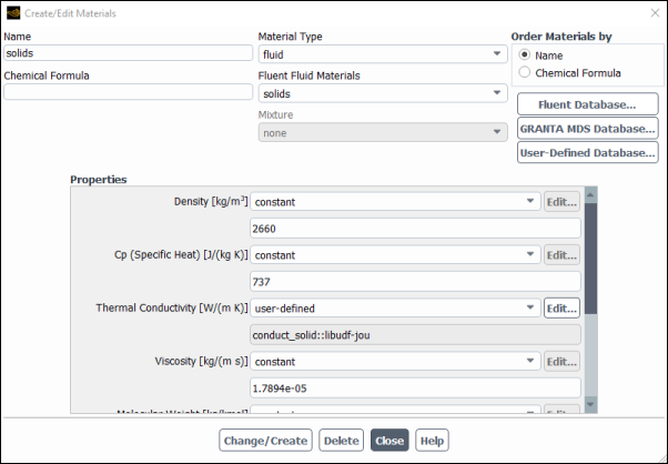
After you have interpreted (Interpreting UDFs) or compiled (Compiling UDFs) your DEFINE_ANISOTROPIC_CONDUCTIVITY UDF, the name of the function you supplied as a DEFINE macro argument will become visible and selectable in the Create/Edit Materials dialog box (Figure 6.13: The Create/Edit Materials Dialog Box) in Ansys Fluent.
To hook the UDF to Ansys Fluent, first open the Materials task page.
Setup →
![]() Materials
Materials
Make a selection in the Materials list and click the Create/Edit... button to open the appropriate Create/Edit Materials dialog box (Figure 6.13: The Create/Edit Materials Dialog Box).
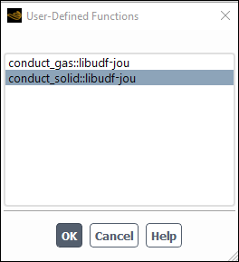
To hook an anisotropic conductivity UDF for the conductivity matrix, select user-defined-anisotropic-k from the Thermal Conductivity drop-down list. The User-Defined Functions dialog box (Figure 6.14: The User-Defined Functions Dialog Box) will open.
Select the name of your UDF (for example, cyl_ortho_cond::libudf) and click in the User-Defined Functions dialog box. The name will then be displayed in the field below the Thermal Conductivity drop-down list in the Create/Edit Materials dialog box. Click Change/Create to save your settings.
See
DEFINE_ANISOTROPIC_CONDUCTIVITY
for details
about defining DEFINE_ANISOTROPIC_CONDUCTIVITY UDFs and the User's
Guide for general information about user-defined anisotropic
conductivity.
After you have interpreted (Interpreting UDFs) or compiled
(Compiling UDFs) your
DEFINE_CAPILLARY_PRESSURE UDF, the name of the function you
supplied as a DEFINE macro argument will become visible and
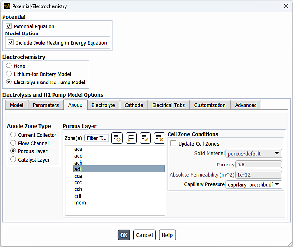
selectable in the Potential/Electrochemistry dialog box (Figure 6.15: The Potential/Electrochemistry Dialog Box - Anode Tab) in Ansys Fluent.
To hook the UDF to Ansys Fluent:
In the Potential/Electrochemistry dialog box go to the Anode or Cathode tab.
For the selected Porous Layer zone, select the name of your UDF (for example, capillary_pre::libudf) from the Capillary Pressure drop-down list.
Your UDF will be applied to the porous layer zone(s) you selected.
See
DEFINE_CAPILLARY_PRESSURE
for details about defining
DEFINE_CAPILLARY_PRESSURE UDFs.
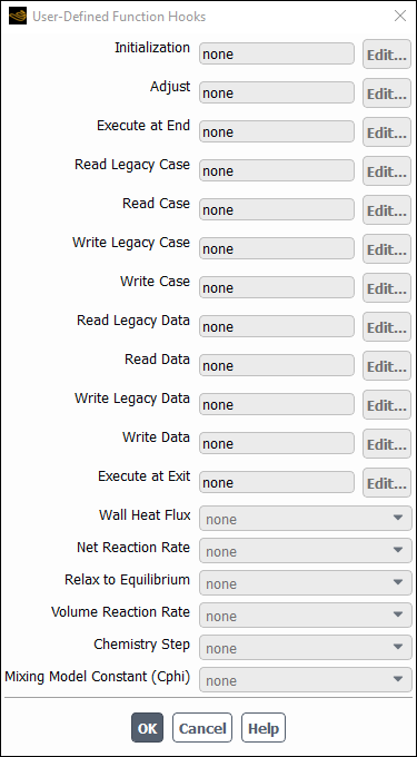
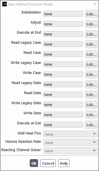
After you have interpreted (Interpreting UDFs) or compiled (Compiling UDFs) your DEFINE_CHEM_STEP UDF, the name of the function you supplied as a DEFINE macro argument will become visible and selectable in the User-Defined Function Hooks dialog box (Figure 6.16: The User-Defined Function Hooks Dialog Box) in Ansys Fluent.
To hook the UDF to Ansys Fluent, first set up the species transport and combustion models in the Species Model dialog box.
Setup → Models → Species
Edit...
Note that chemistry step UDFs can only be used with the laminar finite-rate model (with the stiff chemistry solver), the EDC model, or the PDF Transport model. Therefore, you must use one of the following groups of settings in the Species Model dialog box:
To enable the laminar finite-rate model, select Species Transport, enable Volumetric in the Reactions group box, select Finite-Rate/No TCI in the Turbulence-Chemistry Interaction group box, and select Stiff Chemistry Solver from the Chemistry Solver drop-down list.
To enable the EDC model, select Species Transport, enable Volumetric in the Reactions group box, and select Eddy-Dissipation Concept in the Turbulence-Chemistry Interaction group box.
To enable the PDF Transport model, select Composition PDF Transport and enable Volumetric in the Reactions group box.
Next, open the User-Defined Function Hooks dialog box (Figure 6.16: The User-Defined Function Hooks Dialog Box).
Parameters & Customization → User Defined Functions
Function Hooks...
Select the function name (for example, user_chem_step::libudf) in the Chemistry Step drop-down list in the User-Defined Function Hooks dialog box, and click .
See
DEFINE_CHEM_STEP
for details
about defining DEFINE_CHEM_STEP functions.
After you have interpreted (Interpreting UDFs) or compiled (Compiling UDFs) your DEFINE_CPHI UDF, the name of the function you supplied as a DEFINE macro argument will become visible and selectable in the User-Defined Function Hooks dialog box (Figure 6.17: The User-Defined Function Hooks Dialog Box) in Ansys Fluent.
To hook the UDF to Ansys Fluent, open the User-Defined Function Hooks dialog box (Figure 6.17: The User-Defined Function Hooks Dialog Box).
Parameters & Customization → User Defined Functions
Function Hooks...
Important: EDC or PDF Transport models must be enabled to hook the mixing model constant Cphi UDFs.
Select the function name (for example, user_cphi::libudf) from the drop-down list for Mixing Model Constant (Cphi), and click .
See
DEFINE_CPHI
for details about
defining DEFINE_CPHI functions.
After you have interpreted (Interpreting UDFs) or compiled (Compiling UDFs) your DEFINE_DIFFUSIVITY UDF, the name of the function you supplied as a DEFINE macro argument will become visible and selectable in Ansys Fluent.
To hook the UDF to Ansys Fluent, first open the Materials task page.
Setup →
![]() Materials
Materials
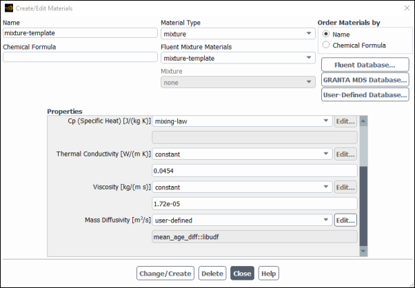
Make a selection in the Materials list and click the Create/Edit... button to open the appropriate Create/Edit Materials dialog box (Figure 6.18: The Create/Edit Materials Dialog Box).
You then have the following options:
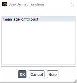
To hook a mass diffusivity UDF for the species transport equations, select user-defined from the Mass Diffusivity drop-down list of the Create/Edit Materials dialog box (Figure 6.18: The Create/Edit Materials Dialog Box). The User-Defined Functions dialog box (Figure 6.19: The User-Defined Functions Dialog Box) will open.
Select the name of your UDF (for example, mean_age_diff::libudf) and click in the User-Defined Functions dialog box. The name will then be displayed in the field below the Mass Diffusivity drop-down list in the Create/Edit Materials dialog box. Click Change/Create to save your settings.
To hook a single diffusion coefficient UDF so that it applies to all UDS equations, first set the number and options of the user-defined scalars using the User-Defined Scalars dialog box.
Parameters & Customization → User Defined Scalars
New...
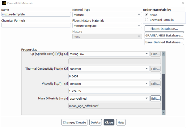
Then, select user-defined from the UDS Diffusivity drop-down list in the Create/Edit Materials dialog box (Figure 6.20: The Create/Edit Materials Dialog Box).
Next, select the name of your UDF (for example, mean_age_diff::libudf) in the User-Defined Functions dialog box that opens (Figure 6.19: The User-Defined Functions Dialog Box) and click . The name will then be displayed in the field below the UDS Diffusivity drop-down list in the Create/Edit Materials dialog box. Click Change/Create to save your settings.
See
DEFINE_DIFFUSIVITY
for details
about defining DEFINE_DIFFUSIVITY UDFs and
the User's Guide for general information about UDS diffusivity.
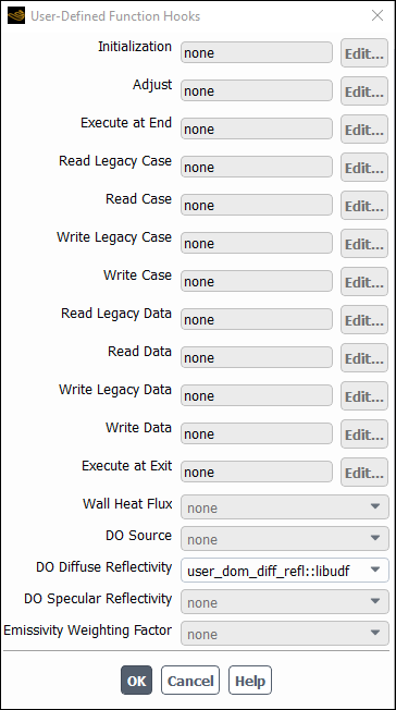
After you have interpreted (Interpreting UDFs) or compiled (Compiling UDFs) your DEFINE_DOM_DIFFUSE_REFLECTIVITY UDF, the name of the function you supplied as a DEFINE macro argument will become visible and selectable in the User-Defined Function Hooks dialog box (Figure 6.21: The User-Defined Function Hooks Dialog Box) in Ansys Fluent.
Important: The discrete ordinates (DO) radiation model must be enabled from the Radiation Model dialog box.
To hook the UDF to Ansys Fluent, open the User-Defined Function Hooks dialog box (Figure 6.21: The User-Defined Function Hooks Dialog Box).
Parameters & Customization → User Defined Functions
Function Hooks...
Select the function name (for example, user_dom_diff_refl::libudf) in the DO Diffuse Reflectivity drop-down list in the User-Defined Function Hooks dialog box, and click .
See
DEFINE_DOM_DIFFUSE_REFLECTIVITY
for details about DEFINE_DOM_DIFFUSE_REFLECTIVITY functions.
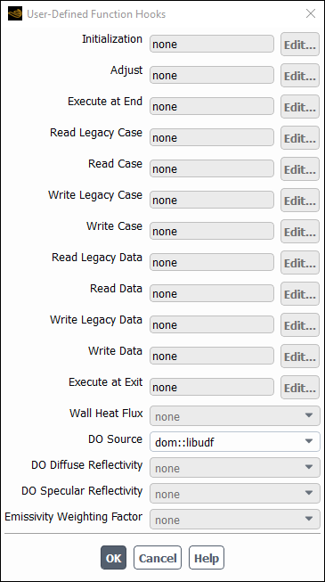
After you have interpreted (Interpreting UDFs) or compiled (Compiling UDFs) your DEFINE_DOM_SOURCE UDF, the name of the function you supplied as a DEFINE macro argument will become visible and selectable in the User-Defined Function Hooks dialog box (Figure 6.22: The User-Defined Function Hooks Dialog Box) in Ansys Fluent.
Important: The discrete ordinates (DO) radiation model must be enabled from the Radiation Model dialog box.
To hook the UDF to Ansys Fluent, open the User-Defined Function Hooks dialog box (Figure 6.22: The User-Defined Function Hooks Dialog Box).
Parameters & Customization → User Defined Functions
Function Hooks...
Select the function name (for example, dom::libudf) in the DO Source drop-down list in the User-Defined Function Hooks dialog box, and click .
See
DEFINE_DOM_SOURCE
for details
about DEFINE_DOM_SOURCE functions.
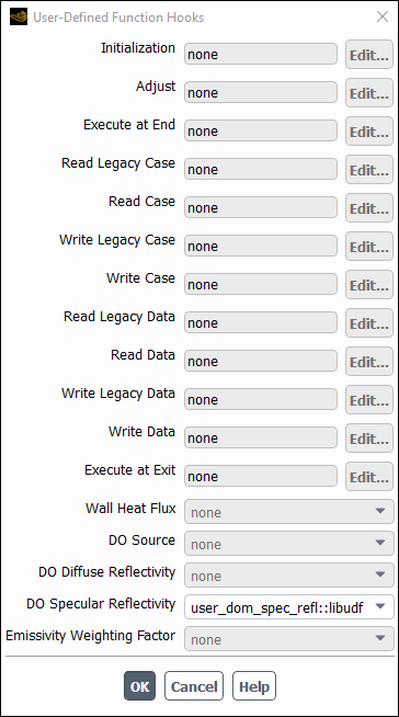
After you have interpreted (Interpreting UDFs) or compiled (Compiling UDFs) your DEFINE_DOM_SPECULAR_REFLECTIVITY UDF, the name of the function you supplied as a DEFINE macro argument will become visible and selectable in the User-Defined Function Hooks dialog box (Figure 6.23: The User-Defined Function Hooks Dialog Box) in Ansys Fluent.
Important: The discrete ordinates (DO) radiation model must be enabled from the Radiation Model dialog box.
To hook the UDF to Ansys Fluent, open the User-Defined Function Hooks dialog box (Figure 6.23: The User-Defined Function Hooks Dialog Box).
Parameters & Customization → User Defined Functions
Function Hooks...
Select the function name (for example, user_dom_spec_refl::libudf) in the DO Specular Reflectivity drop-down list in the User-Defined Function Hooks dialog box, and click .
See
DEFINE_DOM_SPECULAR_REFLECTIVITY
for details about
DEFINE_DOM_SPECULAR_REFLECTIVITY functions.
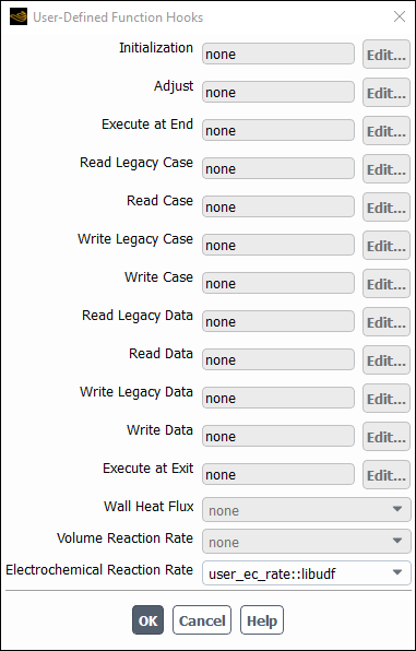
After you have compiled (Compiling UDFs) your DEFINE_EC_RATE UDF, the name of
the function you supplied as a DEFINE macro
argument will become visible and selectable in the User-Defined
Function Hooks dialog box (Figure 6.24: The User-Defined Function Hooks Dialog Box) in Ansys Fluent.
To hook the UDF to Ansys Fluent:
Set up an appropriate reaction model in the Species Model dialog box.
Setup → Models → Species
Edit...
From the Model list, select Species Transport.
In the Reactions group box, enable Volumetric and Electrochemical and click .
Hook the UDF to Ansys Fluent using the User-Defined Function Hooks dialog box (Figure 6.68: The User-Defined Function Hooks Dialog Box).
Parameters & Customization → User Defined Functions
Function Hooks...
From the Electro-Chemical Reaction Rate drop-down list, select the function name (for example,
user_ec_rate::libudf).Click .
See
DEFINE_EC_RATE
for details about
DEFINE_EC_RATE functions.
After you have compiled (Compiling UDFs) your
DEFINE_EC_KINETICS_PARAMETER UDF, the name of the function you
supplied as a DEFINE macro argument will become visible and selectable
in the User-Defined Functions dialog box when you choose
user-defined for a kinetics parameter.
To hook the UDF to Ansys Fluent:
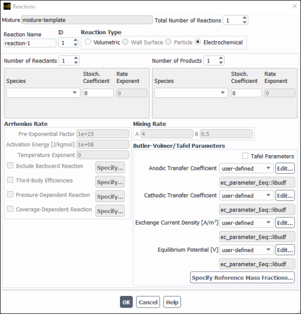
In the Reaction dialog box, select the Electrochemical reaction type.
Define four kinetics parameters for the Butler-Volmer rate equation. For each kinetics parameter that you want to define via your macro, select user-defined from the drop-down list. Next, in the User-Defined Functions dialog box that opens, select the name of your UDF (for example, ec_parameter_Eeq::libudf) and click . The name of the function will be displayed in the field below the selected Butler-Volmer/Tafel parameter.
Click to close the Reaction dialog box.
See
DEFINE_EC_KINETICS_PARAMETER
for details about
DEFINE_EC_KINETICS_PARAMETER functions.
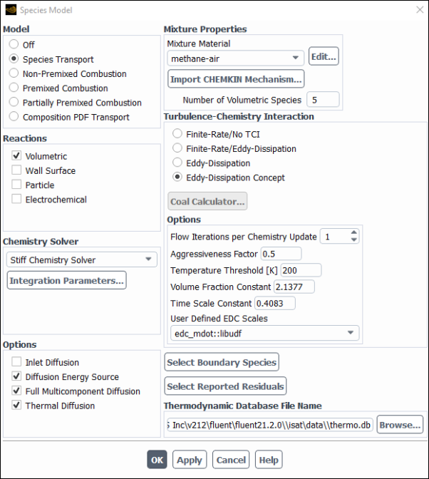
Once the UDF that you have defined using DEFINE_EDC_MDOT is
compiled (Compiling UDFs), the name of the function that you
supplied as a DEFINE macro argument will become visible and
selectable from the User Defined EDC Scales drop-down list in the
Options group box of the Species Model dialog
box in Ansys Fluent (Figure 6.27: The Species Model Dialog Box (User Defined EDC Scales)).
Note:
Note that the UDF hook is only available when the Eddy Dissipation Concept model is selected in the Species Model dialog box.
DEFINE_EDC_MDOTandDEFINE_EDC_SCALEScannot be used together.
To hook the UDF to Ansys Fluent:
In the Species Model dialog box, ensure that Eddy Dissipation Concept is enabled in the Turbulence-Chemistry Interaction group box.
Setting Up Physics → Models → Species...
From the User Defined EDC Scales drop-down list (Options group box), select the function name (for example,
edc_mdot::libudf) and click .
See
DEFINE_EDC_MDOT
for details about
DEFINE_EDC_MDOT functions.
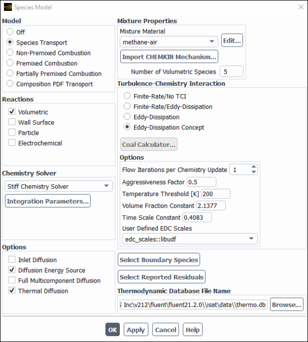
Once the UDF that you have defined using DEFINE_EDC_SCALES is
compiled (Compiling UDFs), the name of the function that you
supplied as a DEFINE macro argument will become visible and
selectable from the User Defined EDC Scales drop-down list in the
Options group box of the Species Model dialog
box in Ansys Fluent (Figure 6.27: The Species Model Dialog Box (User Defined EDC Scales)).
Note:
Note that the UDF hook is only available when the Eddy Dissipation Concept model is selected in the Species Model dialog box.
DEFINE_EDC_MDOTandDEFINE_EDC_SCALEScannot be used together.
To hook the UDF to Ansys Fluent:
In the Species Model dialog box, ensure that Eddy Dissipation Concept is enabled in the Turbulence-Chemistry Interaction group box.
Setting Up Physics → Models → Species...
From the User Defined EDC Scales drop-down list (Options group box), select the function name (for example,
edc_scales::libudf) and click .
See
DEFINE_EDC_SCALES
for details about
DEFINE_EDC_SCALES functions.
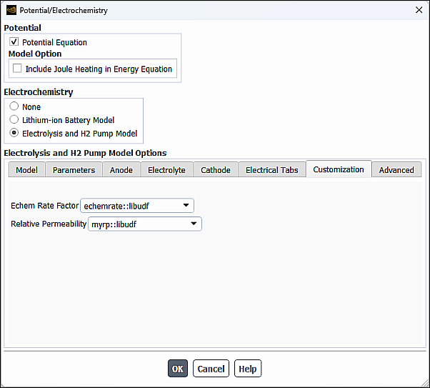
After you have compiled (Compiling UDFs) your
DEFINE_ELECTROLYSIS_ECHEM_RATE UDF, the name of the function you
supplied as a DEFINE macro argument will become visible and
selectable in the Potential/Electrochemistry dialog box (Figure 6.28: The Potential/Electrochemistry Dialog Box - Customization Tab) in Ansys Fluent.
To hook the UDF to Ansys Fluent:
In the Potential/Electrochemistry dialog box go to the Customization tab.
From the Echem Rate Factor drop-down list, select the name of your UDF (for example, echemrate::libudf).
See
DEFINE_ELECTROLYSIS_ECHEM_RATE
for details about defining
DEFINE_ELECTROLYSIS_ECHEM_RATE UDFs.
After you have compiled (Compiling UDFs) your
DEFINE_ELECTROLYSIS_RELATIVE_PERMEABILITY UDF, the name of the
function you supplied as a DEFINE macro argument will become
visible and selectable in the Potential/Electrochemistry dialog box
(Figure 6.28: The Potential/Electrochemistry Dialog Box - Customization Tab) in Ansys Fluent.
To hook the UDF to Ansys Fluent:
In the Potential/Electrochemistry dialog box go to the Customization tab (see Figure 6.28: The Potential/Electrochemistry Dialog Box - Customization Tab.
From the Relative Permeability drop-down list, select the name of your UDF (for example, myrp::libudf).
See
DEFINE_ELECTROLYSIS_RELATIVE_PERMEABILITY
for details about defining
DEFINE_ELECTROLYSIS_RELATIVE_PERMEABILITY UDFs.
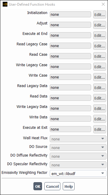
After you have interpreted (Interpreting UDFs) or compiled (Compiling UDFs) your DEFINE_EMISSIVITY_WEIGHTING_FACTOR UDF, the name of the function you supplied as a DEFINE macro argument will become visible and selectable in the User-Defined Function Hooks dialog box (Figure 6.29: The User-Defined Function Hooks Dialog Box) in Ansys Fluent.
Important: In the Radiation Model dialog box, P1 or Discrete Ordinates (DO) must be selected from the Model list, and a nonzero value must be entered for Number of Bands in the Non-Gray Model group box.
To hook the UDF to Ansys Fluent, open the User-Defined Function Hooks dialog box (Figure 6.29: The User-Defined Function Hooks Dialog Box).
Parameters & Customization → User Defined Functions
Function Hooks...
Select the function name (for example, em_wt::libudf) in the Emissivity Weighting Factor drop-down list in the User-Defined Function Hooks dialog box, and click .
See
DEFINE_EMISSIVITY_WEIGHTING_FACTOR
for details about defining DEFINE_EMISSIVITY_WEIGHTING_FACTOR UDFs.
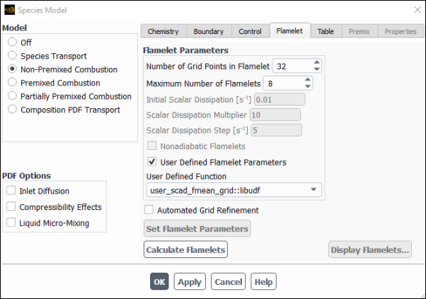
Once the UDF that you have defined using DEFINE_FLAMELET_PARAMETERS is compiled (Compiling UDFs), the name
of the function that you supplied as a DEFINE macro argument will become visible and selectable in the User-Defined Function drop-down list under the Flamelet tab of the Species Model dialog box in Ansys Fluent (Figure 6.30: The Flamelet Tab Dialog Box (User-Defined Flamelet Parameters)).
Note: Note that the UDF hook is only available when either the Non-Premixed Combustion or Partially-Premixed Combustion model is selected in the Species Model dialog box.
Setup → Models → Species
Edit...
To hook the UDF to Ansys Fluent:
In the Species Model dialog box, under the Flamelet tab, select User-Defined Flamelet Parameters.
From the User Defined Function drop-down list, select the function name (for example,
user_scad_fmean_grid ::libudf) and click .
See
DEFINE_FLAMELET_PARAMETERS
for
details about defining DEFINE_FLAMELET_PARAMETERS UDFs.
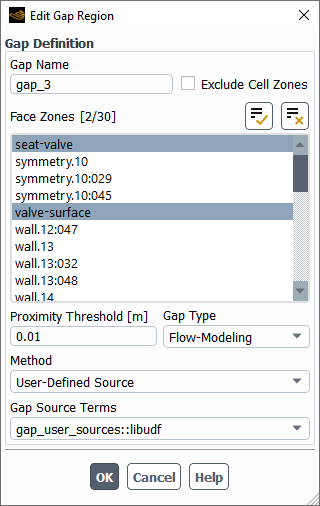
After the UDF that you have defined using
DEFINE_GAP_MODEL_SOURCE is compiled (Compiling UDFs), the name of the function that you supplied as a
DEFINE macro argument will become visible and selectable in the
Gap Source Terms drop-down list of the Edit Gap
Region dialog box in Ansys Fluent (Figure 6.31: The Edit Gap Region Dialog Box ). For
details on accessing the Edit Gap Region dialog box, see Using the Gap Model in the Fluent User's Guide.
To hook the UDF to Ansys Fluent:
In the Edit Gap Region dialog box, select Flow-Modeling from the Gap Type drop-down list.
Select User-Defined Source from the Method drop-down list.
From the Gap Source Terms drop-down list, select the function name (for example,
gap_user_sources::libudf) and click .
See DEFINE_GAP_MODEL_SOURCE
for details about defining
DEFINE_GAP_MODEL_SOURCE UDFs.
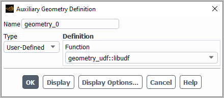
After you have compiled (Compiling UDFs) your
DEFINE_GEOMETRY UDF, the name of the function you supplied as a
DEFINE macro argument will become visible and selectable in the
Auxiliary Geometry Definition dialog box.
To hook the UDF to Ansys Fluent, you will first need to open the Manage Auxiliary Geometry Definitions dialog box from the Outline View.
Setup → Auxiliary Geometry
Definitions
Manage...
Next, click the button in the Manage Auxiliary Geometry Definitions dialog box to open the Auxiliary Geometry Definition dialog box. (Figure 6.32: The Auxiliary Geometry Definition Dialog Box).
Select User-Defined from the Type drop-down list, and select the function name (for example, geometry_udf::libudf) from the Function drop-down list. Click to save the definition and close the dialog box.
See DEFINE_GEOMETRY for details about
DEFINE_GEOMETRY functions.
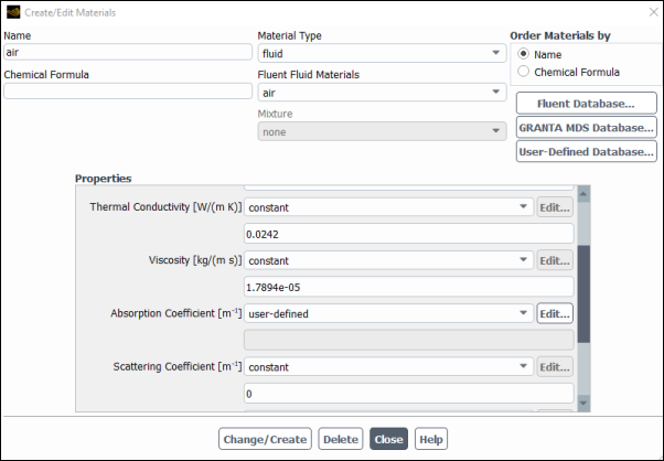
After you have interpreted (Interpreting UDFs) or compiled (Compiling UDFs) your DEFINE_GRAY_BAND_ABS_COEFF UDF, the name of the function you supplied as a DEFINE macro argument will become visible and selectable in the Create/Edit Materials dialog box in Ansys Fluent.
To hook the UDF to Ansys Fluent, first make sure that the Discrete Ordinates (DO) model is selected in the Radiation Model dialog box, with a nonzero Number of Bands in the Non-Gray Model group box. Then open the Materials task page.
Setup →
![]() Materials
Materials
Select the appropriate material from the Material selection list and click the Create/Edit... button to open the Create/Edit Materials dialog box (Figure 6.33: The Create/Edit Materials Dialog Box).
Next, select user-defined-gray-band from the Absorption Coefficient drop-down list in the Create/Edit Materials dialog box. This opens the User-Defined Functions dialog box, where you must select the name of the function (for example, user_gray_band_abs::libudf) and click . Finally, click Change/Create in the Create/Edit Materials dialog box.
See
DEFINE_GRAY_BAND_ABS_COEFF
for
details about DEFINE_GRAY_BAND_ABS_COEFF functions.
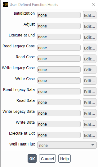
After you have interpreted (Interpreting UDFs) or compiled (Compiling UDFs) your DEFINE_HEAT_FLUX UDF, the name of the function you supplied as a DEFINE macro argument will become visible and selectable in the User-Defined Function Hooks dialog box (Figure 6.34: The User-Defined Function Hooks Dialog Box) in Ansys Fluent.
To hook the UDF to Ansys Fluent, open the User-Defined Function Hooks dialog box (Figure 6.34: The User-Defined Function Hooks Dialog Box).
Parameters & Customization → User Defined Functions
Function Hooks...
Important: The Energy Equation must be enabled.
Select the function name (for example, user_heat_flux::libudf) in the Wall Heat Flux drop-down list in the User-Defined Function Hooks dialog box, and click .
See
DEFINE_HEAT_FLUX
for details
about DEFINE_HEAT_FLUX functions.
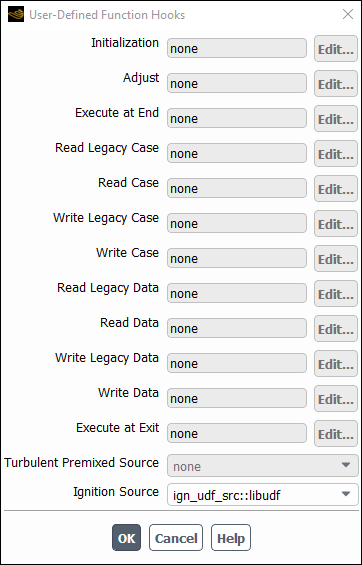
After you have compiled (Compiling UDFs) your DEFINE_IGNITE_SOURCE UDF, the name
of the function you supplied as a DEFINE macro
argument will become visible and selectable in the User-Defined
Function Hooks dialog box (Figure 6.35: The User-Defined Function Hooks Dialog Box) in Ansys Fluent.
To hook the UDF to Ansys Fluent, first open the General task page.
Setup →
![]() General
General
Select Pressure-Based from the Type list, and select Transient from the Time list.
Then, select a turbulence model in the Viscous Model dialog box.
Setup → Models → Viscous Model
Edit...
Next, set up an appropriate reaction model in the Species Model dialog box.
Setup → Models → Species
Edit...
Select either the Premixed Combustion or the Partially Premixed Combustion model in the Species Model dialog box and click .
Then open the Autoignition Model dialog box.
Setup → Models → Species → Autoignition
Edit...
Select the Knock Model from the Model list in the Autoignition Model dialog box, and click .
Next, open the User-Defined Function Hooks dialog box (Figure 6.35: The User-Defined Function Hooks Dialog Box).
Parameters & Customization → User Defined Functions
Function Hooks...
Select the function name (for example, ign_udf_src::libudf) in the Ignition Source drop-down list in the User-Defined Function Hooks dialog box, and click .
See
DEFINE_IGNITE_SOURCE
for details
about DEFINE_IGNITE_SOURCE functions.
After you have interpreted (Interpreting UDFs) or compiled
(Compiling UDFs) your
DEFINE_MASS_TR_PROPERTY UDF, the name of the function you
supplied in the argument of the DEFINE macro will become visible
and selectable in the User-Defined Functions dialog box in
Ansys Fluent.
To hook the UDF:
In the Multiphase Model dialog box, go to the Phase Interaction > Heat, Mass, Reactions > Mass tab and click next to evaporation-condensation.
Setup → Models → Multiphase
Edit...
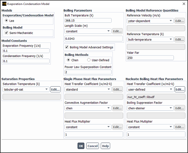
In the Evaporation-Condensation Model dialog box that opens, make sure that the Semi-Mechanistic boiling model is selected (Figure 6.36: The Evaporation-Condensation Model Dialog Box).
Select user-defined in the drop-down list for the appropriate parameter (for example, Heat Transfer Coefficient).
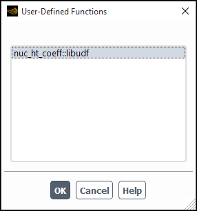
In the User-Defined Functions dialog box, select the function name (for example,
nuc_ht_coeff) from the list of UDFs displayed and click .The name of the function will subsequently be displayed under the selected parameter (for example, Heat Transfer Coefficient) in the Evaporation-Condensation Model dialog box (Figure 6.36: The Evaporation-Condensation Model Dialog Box).
See
DEFINE_MASS_TR_PROPERTY
for details about
DEFINE_MASS_TR_PROPERTY functions.
After you have compiled (Compiling UDFs) your DEFINE_NET_REACTION_RATE UDF, the
name of the function you supplied as a DEFINE macro argument will become visible and selectable in the User-Defined Function Hooks dialog box (Figure 6.38: The User-Defined Function Hooks Dialog Box) in Ansys Fluent.
To hook the UDF to Ansys Fluent, first set up the species transport and combustion models.
Setup → Models → Species
Edit...
Note that net reaction rate UDFs can only be used with the laminar finite-rate model (with the stiff chemistry solver), the EDC model, the PDF Transport model, or the surface chemistry model. Therefore, you must use one of the following groups of settings in the Species Model dialog box:
To enable the laminar finite-rate model, select Species Transport, enable Volumetric in the Reactions group box, select Finite-Rate/No TCI in the Turbulence-Chemistry Interaction group box, and select Stiff Chemistry Solver from the Chemistry Solver drop-down list.
To enable the EDC model, select Species Transport, enable Volumetric in the Reactions group box, and select Eddy-Dissipation Concept in the Turbulence-Chemistry Interaction group box.
To enable the PDF Transport model, select Composition PDF Transport and enable Volumetric in the Reactions group box.
To enable the surface chemistry model, select Species Transport and enable Volumetric and Wall Surface in the Reactions group box.
Next, open the User-Defined Function Hooks dialog box (Figure 6.38: The User-Defined Function Hooks Dialog Box).
Parameters & Customization → User Defined Functions
Function Hooks...
Select the function name (for example, net_rxn::libudf) in the Net Reaction Rate Function drop-down list, and click .
See
DEFINE_NET_REACTION_RATE
for
details about DEFINE_NET_REACTION_RATE functions.
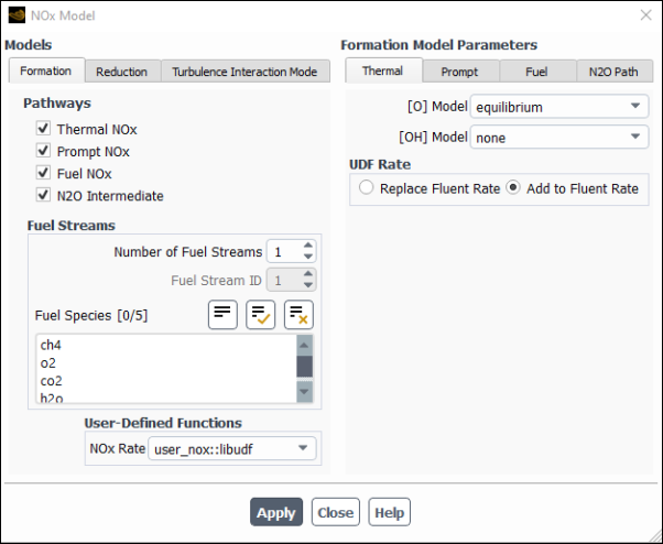
After you have compiled (Compiling UDFs) your DEFINE_NOX_RATE UDF in Ansys Fluent,
the function name you supplied in the DEFINE macro argument will become visible and selectable in the NOx Rate drop-down list in the Formation tab of the NOx Model dialog box (Figure 6.39: The NOx Model Dialog Box).
Setup → Models → Species → NOx
Edit...
Recall that a single UDF is used to define custom rates for
the thermal NOx, prompt NOx, fuel NOx, and O NOx pathways. By default,
the custom NOx rate of your UDF is added to the rate calculated internally
by Ansys Fluent for each pathway. The UDF rate will be added to the forward
rate if it is assigned to the
POLLUT_FRATE macro, or the reverse rate if it is assigned to the POLLUT_RRATE macro. If you would rather entirely replace
the internally calculated NOx rate with your custom rate, click the
desired NOx pathway tab (Thermal, Prompt, Fuel, or N2O Path) under Formation Model Parameters, select Replace Fluent Rate in the UDF Rate group box for that pathway,
and then click Apply. Repeat this process for
all of the remaining NOx pathways.
Unless specifically defined in your NOx rate UDF, data and parameter settings for each individual NOx pathway will be derived from the settings in the NOx Model dialog box. Therefore, it is good practice to make the appropriate settings in the NOx Model dialog box, even though you can use a UDF to replace the default rates with user-specified rates. There is no computational penalty for doing this because the default rate calculations will be ignored when Replace Fluent Rate is selected.
To specify a custom maximum limit () for the integration of the temperature PDF for
each cell, you must first select the UDF name (for example, user_nox::libudf) from the NOx Rate drop-down list, as described previously. Then, click the Turbulence Interaction Mode tab and select either temperature or temperature/species from the PDF Mode drop-down list. Finally,
select user-defined from the Tmax Option drop-down list and click Apply.
See
DEFINE_NOX_RATE
for details
about DEFINE_NOX_RATE functions.
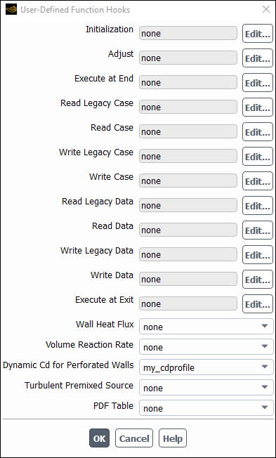
After you have compiled (Compiling UDFs) your
DEFINE_PERFORATED_CD UDF, the name of the function you supplied
as a DEFINE macro argument will become visible and selectable in
the User-Defined Function Hooks dialog box (Figure 6.40: The User-Defined Function Hooks Dialog Box) in Ansys Fluent.
To hook the UDF to Ansys Fluent:
In the User-Defined Function Hooks dialog box, select the function name (for example, my_cdprofile::libudf) in the Dynamic CD for Perforated Walls drop-down list (Figure 6.40: The User-Defined Function Hooks Dialog Box).
Parameters & Customization → User Defined Functions
Function Hooks...
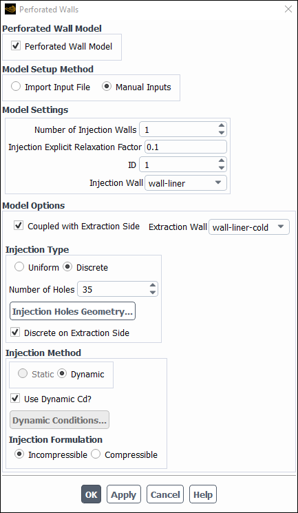
In the Perforated Walls dialog box, configure the appropriate settings for your case. Make sure that the following options are selected:
Discrete (as the injection type)
Dynamic (as the injection method)
Discrete on Extraction Side
Setup →
 Boundary
Conditions → Perforated Walls...
Boundary
Conditions → Perforated Walls...Select Use Dynamic Cd?
Note: Only one DEFINE_PERFORATED_CD can be hooked. That is, if you are
using a DEFINE_PERFORATED_CD UDF for multiple injections, the
same UDF will be used for each injection.
See
DEFINE_PERFORATED_CD
for details about defining
DEFINE_PERFORATED_CD functions.
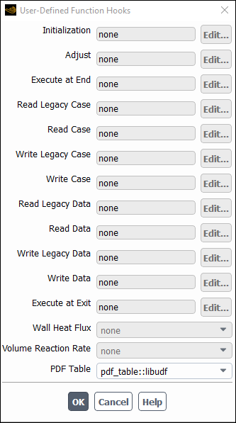
After you have compiled (Compiling UDFs) your DEFINE_PDF_TABLE UDF, the name of
the function you supplied as a DEFINE macro
argument will become visible and selectable in the User-Defined
Function Hooks dialog box (Figure 6.42: The User-Defined Function Hooks Dialog Box) in Ansys Fluent.
To hook the UDF to Ansys Fluent, open the User-Defined Function Hooks dialog box (Figure 6.43: The User-Defined Function Hooks Dialog Box).
Parameters & Customization → User Defined Functions
Function Hooks...
Important: You must enable the Non-Premixed or Partially-Premixed models, and generate or read a valid PDF table.
Select the function name (for example, pdf_table::libudf) in the PDF Table drop-down list in the User-Defined Function Hooks dialog box, and click .
See
DEFINE_PDF_TABLE
for details
about defining DEFINE_PDF_TABLE functions.
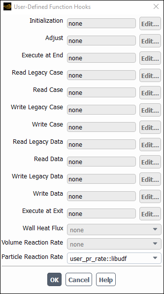
After you have interpreted (Interpreting UDFs) or compiled (Compiling UDFs) your DEFINE_PR_RATE UDF, the name of the function you supplied as a DEFINE macro argument will become visible and selectable in the User-Defined Function Hooks dialog box (Figure 6.43: The User-Defined Function Hooks Dialog Box) in Ansys Fluent.
To hook the UDF to Ansys Fluent, open the User-Defined Function Hooks dialog box (Figure 6.43: The User-Defined Function Hooks Dialog Box).
Parameters & Customization → User Defined Functions
Function Hooks...
Important: You must enable the particle surface reactions option before you can hook the UDF by selecting Volumetric and Particle Surface under Reactions in the Species Model dialog box.
Select the function name (for example, user_pr_rate::libudf) in the Particle Reaction Rate Function drop-down list in the User-Defined Function Hooks dialog box, and click .
See
DEFINE_PR_RATE
for details
about defining DEFINE_PR_RATE functions.
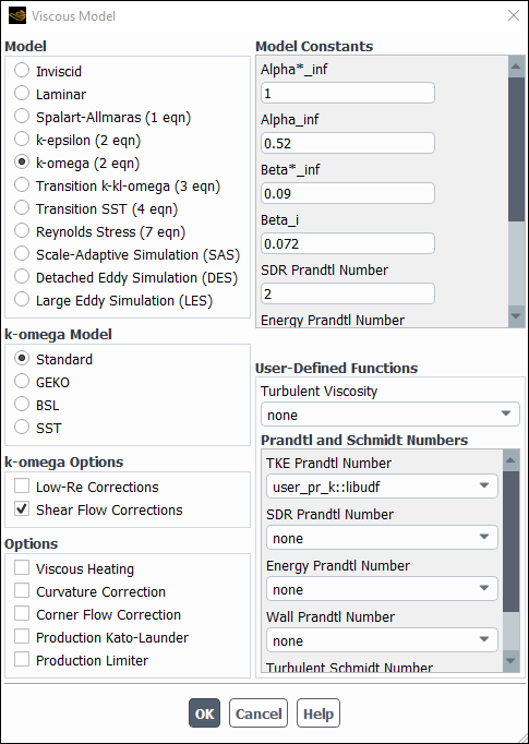
After you have interpreted (Interpreting UDFs) or compiled (Compiling UDFs) your DEFINE_PRANDTL UDF, the name of the function you supplied as a DEFINE macro argument will become visible and selectable in the Viscous Model dialog box (Figure 6.44: The Viscous Model Dialog Box) in Ansys Fluent.
Setup → Models → Viscous
Edit...
To hook the UDF to Ansys Fluent, select the function name (for example, user_pr_k::libudf) from the TKE Prandtl Number drop-down list under User-Defined Functions in the Viscous Model dialog box, and click .
See
DEFINE_PRANDTL UDFs for details
about DEFINE_PRANDTL functions.
After you have interpreted (Interpreting UDFs) or compiled (Compiling UDFs) your DEFINE_PROFILE UDF, the name of the function you supplied as a DEFINE macro argument will become visible and selectable in the appropriate
boundary zone condition dialog box, cell zone condition dialog box,
or Shell Conduction Layers dialog box in Ansys Fluent.
To open the boundary or cell zone condition dialog box, select the
zone in the Boundary Conditions or Cell Zone Conditions task page and click the Edit... button.
Setup →
![]() Boundary Conditions
Boundary Conditions
or
Setup →
![]() Cell Zone Conditions
Cell Zone Conditions
To open the Shell Conduction Layers dialog box, enable the Shell Conduction option in the Thermal tab of the Wall dialog box, and then click the button.
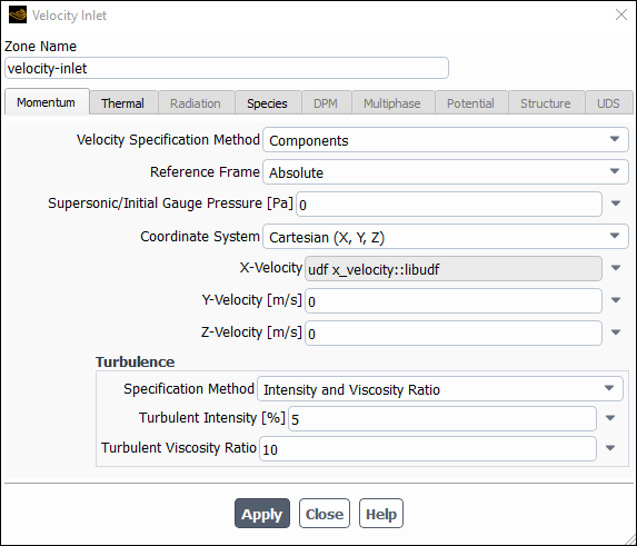
To hook the UDF, select the name of your function in the appropriate drop-down list. For example, if your UDF defines a velocity inlet boundary condition, click the Momentum tab in the Velocity Inlet dialog box (Figure 6.45: The Velocity Inlet Dialog Box), select the function name (for example, x_velocity::libudf) from the X Velocity drop-down list, and click . Note that the UDF name that is displayed in the drop-down lists is preceded by the word udf (for example, udf x_velocity::libudf).
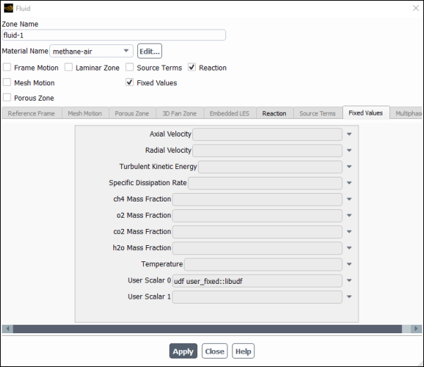
If you are using your UDF to specify a fixed value in a cell zone, you will need to turn on the Fixed Values option in the Fluid or Solid dialog box. Then click the Fixed Values tab and select the name of the UDF in the appropriate drop-down list for the value you want to set.
See
DEFINE_PROFILE
for details
about DEFINE_PROFILE functions.
For each of the N scalar equations you have specified in your Ansys Fluent model using the User-Defined Scalars dialog box, you can hook a fixed-value UDF for a cell zone (for example, Fluid or Solid) and a specified-value or flux UDF for all wall, inflow, and outflow boundaries.
After you have interpreted (Interpreting UDFs) or compiled (Compiling UDFs) your DEFINE_PROFILE UDF, the name of the function you supplied as a DEFINE macro argument will become visible and selectable in the appropriate
boundary or cell zone condition dialog box in Ansys Fluent. To open the
boundary or cell zone condition dialog box, select the zone in the Boundary Conditions or Cell Zone Conditions task page and click the Edit... button.
Setup →
![]() Boundary Conditions
Boundary Conditions
or
Setup →
![]() Cell Zone Conditions
Cell Zone Conditions
If you are using your UDF to specify a fixed value in a cell zone, you will need to enable the Fixed Values option in the Fluid or Solid dialog box. Then click the Fixed Values tab (Figure 6.46: The Fluid Dialog Box with Fixed Value Inputs for User-Defined Scalars) and select the name of the UDF (for example, fixed_scalar_0) in the appropriate drop-down list for the value you want to set.
If you are using your UDF to define a specific value or flux for a scalar equation in a boundary condition dialog box, you will first need to enter a nonzero number in the User-Defined Scalars field in the User-Defined Scalars dialog box.
Parameters & Customization → User Defined Scalars
Edit...
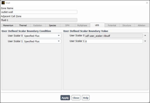
Next, select the UDS tab in the wall, inflow, or outflow boundary dialog box (Figure 6.47: The Wall Dialog Box with Inputs for User-Defined Scalars).
For each UDS (User Scalar 0, User Scalar 1, and so on) specify the boundary condition value as a constant value or a UDF (for example, user_scalar::libudf) in the User-Defined Scalar Boundary Value group box. If you select Specified Flux in the User-Defined Scalar Boundary Condition group box for a particular UDS, then your input will be the value of the flux at the boundary (that is, the dot product of the negative of the term in parentheses on the left hand side of Equation 1–9 (in the Theory Guide) with the vector that is normal to the domain); if you instead select Specified Value, then your input will be the value of the scalar itself at the boundary. In the sample dialog box shown previously, for example, the Specified Value for User Scalar 0 is set to a
user_scalarUDF.Note that for interior walls, you will need to select Coupled Boundary if the scalars are to be solved on both sides of a two-sided wall. Note that the Coupled Boundary option will show up only in the drop-down list when all zones is selected for Solution Zones in the User-Defined Scalars dialog box.
Important: In some cases, you may want to exclude diffusion of the scalar at the inlet of your domain. You can do this by disabling Inlet Diffusion for the scalar in the User-Defined Scalars dialog box.
See
DEFINE_PROFILE
for details
about DEFINE_PROFILE functions.
After you have interpreted (Interpreting UDFs) or compiled (Compiling UDFs) your material property UDF,
the name of the function you supplied as a DEFINE macro argument will become visible and selectable in Ansys Fluent.
There are various dialog boxes in which you can activate a
DEFINE_PROPERTY UDF (for example, Multiphase
Model dialog box), and so the method for hooking it will depend on the property
being defined. The following is an example of hooking a UDF that defines viscosity.
First, open the Materials task page.
Setup →
![]() Materials
Materials
Select the appropriate material from the Material selection list and click the Create/Edit... button to open the Create/Edit Materials dialog box (Figure 6.48: The Create/ Edit Materials Dialog Box).
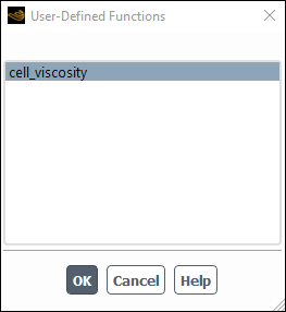
Next, open the User-Defined Functions dialog box (Figure 6.49: The User-Defined Functions Dialog Box) by choosing user-defined in the drop-down list for the appropriate property (for example, Viscosity) in the Create/Edit Materials dialog box. Then select the function name (for example, cell_viscosity::libudf) from the list of UDFs displayed in the User-Defined Functions dialog box and click . The name of the function will subsequently be displayed under the selected property in the Create/Edit Materials dialog box.
Important: If you plan to define density using a UDF, note that the solution convergence will become poor as the density variation becomes large. Specifying a compressible law (density as a function of pressure) or multiphase behavior (spatially varying density) may lead to divergence. It is recommended that you restrict the use of UDFs for density to weakly compressible flows with mild density variations.
See
DEFINE_PROPERTY UDFs for details
about DEFINE_PROPERTY functions.
After you have compiled (Compiling UDFs) your DEFINE_REACTING_CHANNEL_BC UDF,
the name of the function you supplied as a DEFINE macro argument will become visible and selectable in the User Defined Function drop-down list under the Group Inlet Conditions tab of the Reacting Channel
Model dialog box in Ansys Fluent. Note that the UDF hook is
only available when the User Defined Inlet Conditions option is selected.
Setup → Models → Reacting Channel Model
Edit...
Select the function name (for example, tube3_bc_from_1_and_2::libudf) from the User Defined Function drop-down list under the Group Inlet Conditions tab and click Apply.
See
DEFINE_REACTING_CHANNEL_BC
for details about defining DEFINE_REACTING_CHANNEL_BC
functions.
After you have compiled (Compiling UDFs) your DEFINE_REACTING_CHANNEL_SOLVER UDF,
the name of the function you supplied as a DEFINE macro argument will become visible and selectable in the User-Defined Function Hooks dialog box (Figure 6.50: The User-Defined Function Hooks Dialog Box) in Ansys Fluent.
To hook the UDF to Ansys Fluent, open the User-Defined Function Hooks dialog box.
Parameters & Customization → User Defined Functions
Function Hooks...
Important: You must enable the Reacting Channel Model first before hooking your UDF.
Select the function name (for example, set_channel_htc::libudf) in the Reacting Channel Solver drop-down list in the User-Defined Function Hooks dialog box, and click .
See
DEFINE_REACTING_CHANNEL_SOLVER
for details
about defining DEFINE_REACTING_CHANNEL_SOLVER functions.
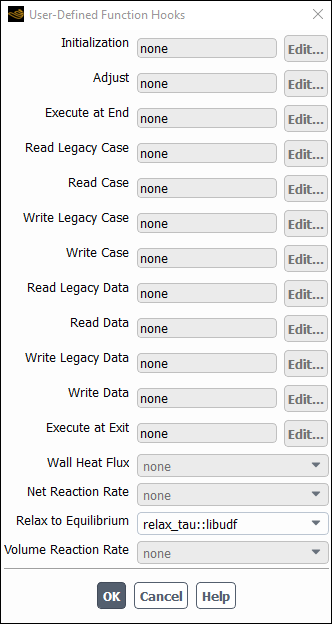
After you have interpreted or compiled your DEFINE_RELAX_TO_EQUILIBRIUM UDF, the name of the function you supplied as a DEFINE macro argument will become visible and selectable in the User-Defined Function Hooks dialog box (Figure 6.51: The User-Defined Function Hooks Dialog Box).
To hook the UDF to Ansys Fluent:
Set up the species transport model.
Setting Up Physics → Models → Species...
Enable Volumetric in the Reactions group box.
Select Relax to Chemical Equilibrium from the Chemistry Solver drop-down list.
Open the User-Defined Function Hooks dialog box.
User Defined → User Defined → Function Hooks...
Select the function name (for example,
relax_tau::libudf) from the Relax to Equilibrium drop-down list, and click OK.
See
DEFINE_RELAX_TO_EQUILIBRIUM
for details about DEFINE_RELAX_TO_EQUILIBRIUM functions.
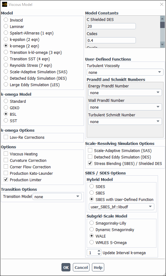
After you have interpreted (Interpreting UDFs) or compiled (Compiling UDFs) your DEFINE_SBES_BF UDF, the name of the function you supplied as a DEFINE macro argument will become visible and selectable in the Viscous Model dialog box in Ansys Fluent.
To hook the UDF to the 3D version of Ansys Fluent, you must first right-click the General branch of the tree and select Transient from the Analysis Type sub-menu.
Setup → General
Analysis Type → Transient
Next, open the Viscous Model dialog box.
Setup → Models → Viscous
Edit...
Select either k-omega or Transition SST from the Model list, and (for k-omega) either BSL or SST from the k-omega Model list. Next, enable the Stress Blending (SBES) / Shielded DES option, and in the Hybrid Model group box select SBES with User-Defined Function and then the function name (for example, user_SBES_bf::libudf) from the drop-down list.
See
DEFINE_SBES_BF
for details about DEFINE_SBES_BF functions.
After you have interpreted (Interpreting UDFs) or compiled (Compiling UDFs) your DEFINE_SCAT_PHASE_FUNC UDF, the name of the function you supplied as a DEFINE macro argument will become visible and selectable in the User-Defined Functions dialog box in Ansys Fluent.
To hook the UDF to Ansys Fluent, first make sure that the Discrete Ordinates (DO) model is selected in the Radiation Model dialog box. Then open the Materials task page.
Setup →
![]() Materials
Materials
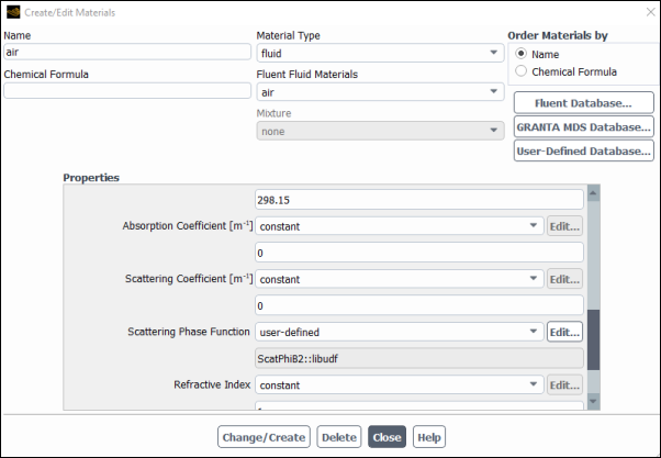
Select the appropriate material from the Material selection list and click the Create/Edit... button to open the Create/Edit Materials dialog box (Figure 6.53: The Create/Edit Materials Dialog Box).
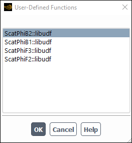
Open the User-Defined Functions dialog box (Figure 6.54: The User-Defined Functions Dialog Box) from the Create/Edit Material dialog box by selecting user-defined in the drop-down list for the Scattering Phase Function property. Then, select the function name (for example, ScatPhiB2) from the list of UDFs displayed in the User-Defined Functions dialog box, and click . The name of the function will subsequently be displayed under the Scattering Phase Function property in the Create/Edit Materials dialog box.
See
DEFINE_SCAT_PHASE_FUNC
for
details about DEFINE_SCAT_PHASE_FUNC functions.
After you have interpreted (Interpreting UDFs) or compiled (Compiling UDFs) your DEFINE_SOLAR_INTENSITY UDF, the name of the function you supplied in the argument of the
DEFINE macro will become visible and selectable
in the User-Defined Functions dialog box in Ansys Fluent.
To hook the UDF, first open the Radiation Model dialog box (Figure 6.55: The Radiation Model Dialog Box).
Setup → Models → Radiation
Edit...
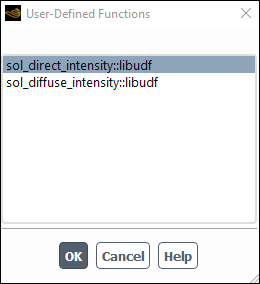
Select Discrete Ordinates (DO) from the Model list, and select Solar Ray Tracing in the Solar Load group box. In the Illumination Parameters group box that appears, select user-defined from the Direct Solar Irradiation or Diffuse Solar Irradiation drop-down list to open the User-Defined Functions dialog box (Figure 6.56: The User-Defined Functions Dialog Box).
Select the function name (for example, sol_direct_intensity::libudf) from the list of UDFs displayed in the User-Defined Functions dialog box and click . The name of the function will subsequently be displayed under the selected property (for example, Direct Solar Irradiation) in the Radiation Model dialog box (Figure 6.55: The Radiation Model Dialog Box).
See
DEFINE_SOLAR_INTENSITY
for
details about DEFINE_SOLAR_INTENSITY functions.
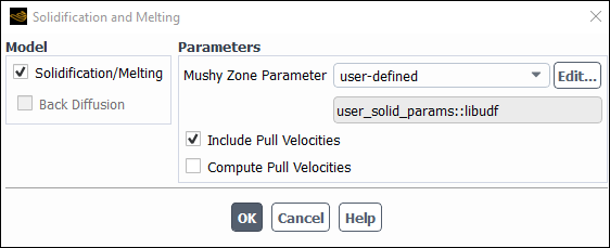
After you have interpreted (Interpreting UDFs) or compiled (Compiling UDFs) your DEFINE_SOLIDIFICATION_PARAMS UDF, the name of the function you supplied in the argument of the
DEFINE macro will become visible and selectable
in the User-Defined Functions dialog box in Ansys Fluent.
To hook the UDF, first open the Solidification and Melting dialog box (Figure 6.57: The Solidification and Melting Dialog Box).
Setup → Models → Solidification & Melting
Edit...
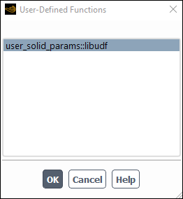
Enable Solidification/Melting under Model. Select user-defined from the Mushy Zone Parameter drop-down list to open the User-Defined Functions dialog box (Figure 6.58: The User-Defined Functions Dialog Box). You can also select user-defined from the Mush Zone Parameter drop-down list.
Select the function name (for example, user_solid_params::libudf) from the list of UDFs displayed in the User-Defined Functions dialog box and click . The name of the function will subsequently be displayed under the selected property.
See
DEFINE_SOLIDIFICATION_PARAMS
for
details about DEFINE_SOLIDIFICATION_PARAMS functions.
After you have interpreted (Interpreting UDFs) or compiled (Compiling UDFs) your DEFINE_SOURCE UDF, the name of the function you supplied as a DEFINE macro argument will become visible and selectable in a source term
dialog box (for example, the Mass sources dialog
box) in Ansys Fluent.
To hook the UDF to Ansys Fluent, you will first need to open the Cell Zone Conditions task page.
Setup →
![]() Cell Zone Conditions
Cell Zone Conditions
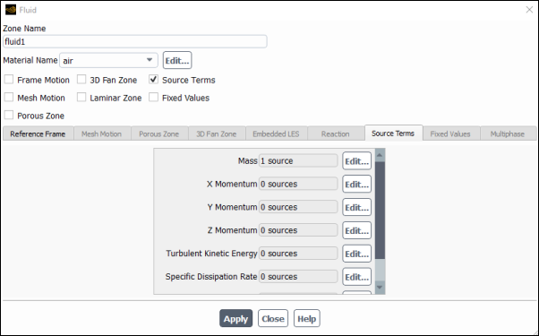
Select the appropriate zone in the Zone selection list of the Cell Zone Conditions task page and click the Edit... button to open the cell zone condition dialog box (for example, the Fluid dialog box, as shown in Figure 6.59: The Fluid Dialog Box).
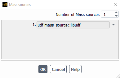
Next, enable the Source Terms option in the cell zone condition dialog box and click the Source Terms tab. This will display the source term parameters (mass, momentum, and so on) in the scrollable window. Click the Edit... button next to the source term (for example, Mass) you want to customize, in order to open the appropriate source term dialog box (for example, the Mass sources dialog box, as shown in Figure 6.60: The Mass sources Dialog Box).
Specify the number of terms you want to model by setting the Number of Mass
Sources text-entry box (for example, 1) and then
select the function name (for example, mass_source::libudf) from the
appropriate drop-down list.
(Note that the UDF name that is displayed in the drop-down lists is preceded by the word udf.) Click in the Mass sources dialog box to accept the new boundary condition. The source term field in the cell zone condition dialog box will display the number of sources (for example, 1 source). Click to close the cell zone condition dialog box and fix the new mass source terms for the solution calculation.
Repeat this step for all of the source terms you want to customize using a UDF.
See
DEFINE_SOURCE
for details
about DEFINE_SOURCE functions.
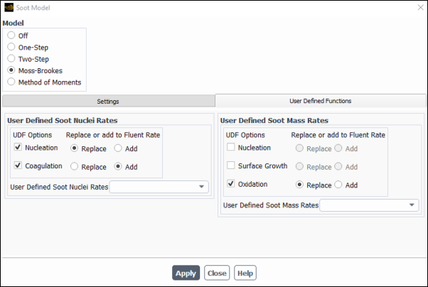
After you have compiled (Compiling UDFs) your
DEFINE_SOOT_MASS_RATES UDF in Ansys Fluent, the function name you supplied
as a DEFINE macro argument will become visible and selectable from
the User Defined Soot Mass Rates drop-down list under the
User Defined Functions tab of the Soot Model dialog
box (Figure 6.61: The Soot Model Dialog Box (User-Defined Mass and Nucleation
Rates)).
Note: The UDF hook is only available when the Moss-Brookes or the Moss-Brookes-Hall soot model is enabled.
Setup → Models → Species → Soot
Edit... → Moss-Brookes
Under the User Defined Functions tab, select
the function name (for example, user_soot_mass_rates::libudf) from the User Defined Soot Mass Rates drop-down
list, and click Apply.
See DEFINE_SOOT_MASS_RATES for details about defining DEFINE_SOOT_MASS_RATES functions.
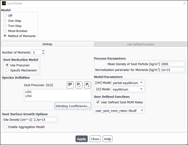
After you have compiled (Compiling UDFs) your
DEFINE_SOOT_MOM_RATES UDF in Ansys Fluent, the function name you
supplied as a DEFINE macro argument will become visible and
selectable from the User Defined Soot MOM Rates drop-down list
(User Defined Functions group box) in the Soot
Model dialog box (Figure 6.62: The Soot Model Dialog Box (User-Defined Soot MOM Rates)).
Note: The UDF hook is only available for the Method of Moments soot model.
To hook a soot MOM rates UDF:
Open the Soot Model dialog box
Setup → Models → Species → Soot
Edit...
Make sure that the Method of Moments is selected as the Model.
Select the function name (for example,
user_soot_mom_rates::libudf) from the User Defined Soot MOM Rates drop-down list.Click .
See DEFINE_SOOT_MOM_RATES for details about defining
DEFINE_SOOT_MOM_RATES functions.
After you have compiled (Compiling UDFs), your DEFINE_SOOT_NUCLEATION_RATES UDF
in Ansys Fluent, the function name you supplied as a DEFINE macro argument will become visible and selectable from the User Defined Soot Nuclei Rates drop-down list under the User Defined Functions tab of the Soot Model dialog box (Figure 6.61: The Soot Model Dialog Box (User-Defined Mass and Nucleation
Rates)).
Note: The UDF hook is only available when the Moss-Brookes or the Moss-Brookes-Hall soot model is enabled.
Setup → Models → Species → Soot
Edit... → Moss-Brookes
Under the User Defined Functions tab, select
the function name (for example, user_soot_nuc_rates::libudf) from the User Defined Soot Nuclei Rates drop-down
list, and click Apply.
See DEFINE_SOOT_NUCLEATION_RATES for details about defining DEFINE_SOOT_NUCLEATION_RATES functions.
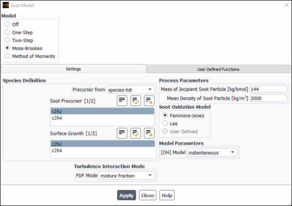
After you have compiled (Compiling UDFs), your DEFINE_SOOT_OXIDATION_RATE UDF
in Ansys Fluent, the function name you supplied as a DEFINE macro argument will become visible and selectable from the User Defined Oxidation Rate drop-down list in the Soot Oxidation Model group box of the Soot Model dialog box (Figure 6.63: The Soot Model Dialog Box (User-Defined Oxidation Rate)).
Note: The UDF hook is only available when the Moss-Brookes or Moss-Brookes-Hall model is enabled.
Setup → Models → Species → Soot
Edit... → Moss-Brookes
Select User Defined in the Soot Oxidation Model group box, then select the function name (for example, user_soot_oxid_rate::libudf) from the User Defined Oxidation Rate drop-down list , and click Apply.
See DEFINE_SOOT_OXIDATION_RATE for details about defining DEFINE_SOOT_OXIDATION_RATE functions.
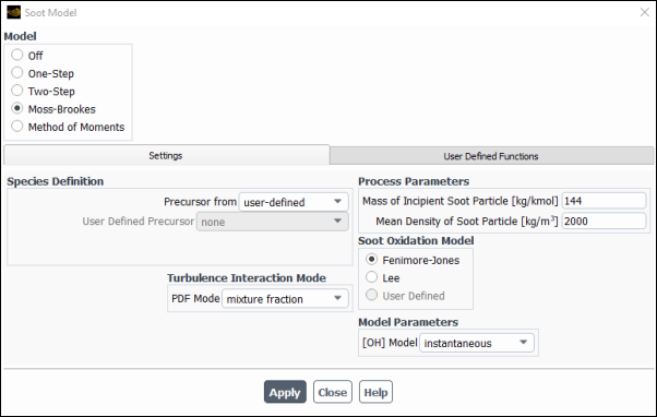
After you have compiled (Compiling UDFs), your DEFINE_SOOT_PRECURSOR UDF in Ansys Fluent,
the function name you supplied as a DEFINE macro argument will become visible and selectable from the User Defined Precursor drop-down list in the Species Definition group box of the Soot Model dialog box ().
Note: The UDF is available only with Moss-Brookes model and visible when the user-defined option is selected from the Precursor from drop-down list in Species Definition group box of the Soot Model dialog box (Figure 6.64: The Soot Model Dialog Box (User-Defined Precursor)).
Setup → Models → Species → Soot
Edit... → Moss-Brookes
Select the function name (for example, user_soot_prec::libudf) from the User Defined Precursor drop-down list in the Species Definition group box, and click Apply.
See DEFINE_SOOT_PRECURSOR for details about defining DEFINE_SOOT_PRECURSOR functions.
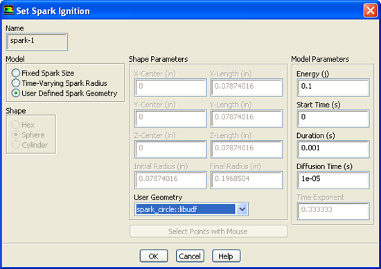
After you have compiled (Compiling UDFs) your DEFINE_SPARK_GEOM UDF, the name
of the function you supplied as a DEFINE macro
argument will become visible and selectable in the Set Spark
Ignition dialog box (Figure 6.65: The Set Spark Ignition Dialog Box) in Ansys Fluent.
To hook the UDF to Ansys Fluent, begin by opening the Species Model dialog box.
Setup → Models → Species
Edit...
In the Species Model dialog box, either select Species Transport from the Model list and enable the Volumetric option in the Reactions list, or simply select Premixed Combustion from the Model list.
Next, open the Spark Ignition dialog box.
Setup → Models → Species → Spark
Ignition
Edit...
Make sure that Number of Sparks is set to a nonzero number in the Spark Ignition dialog box and click the Define... button for the spark you want to define, in order to open the Set Spark Ignition dialog box.
In the Set Spark Ignition dialog box, select User Defined Spark Geometry from the Model list. Then select the function name (for example, spark_circle::libudf) from the User Geometry drop-down list in the Shape Parameters group box.
See
DEFINE_SPARK_GEOM (R14.5 spark model)
for details
about DEFINE_SPARK_GEOM UDFs.
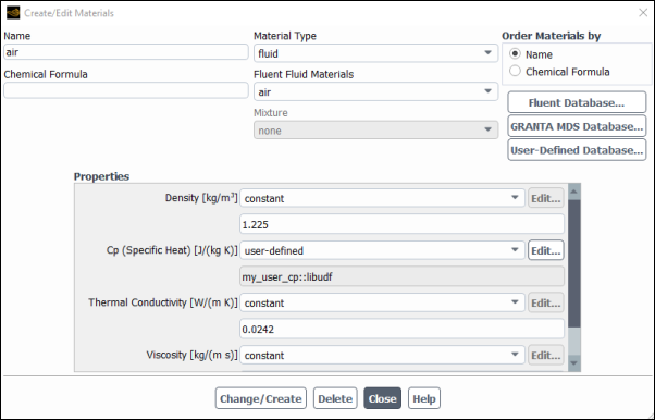
After you have compiled your DEFINE_SPECIFIC_HEAT UDF (as described in Compiling UDFs),
the name of the function you supplied as a DEFINE macro argument will become visible and selectable in Ansys Fluent.
To hook the UDF to Ansys Fluent, you will first need to open the Materials task page.
Setup →
![]() Materials
Materials
Select the appropriate material from the Material selection list and click the Create/Edit... button to open the Create/Edit Materials dialog box (Figure 6.66: The Create/Edit Materials Dialog Box).
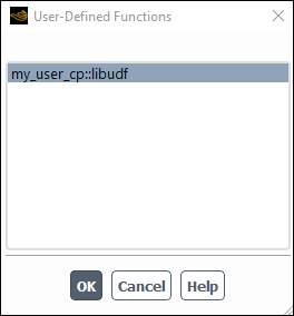
Next, select user-defined from the drop-down list for Cp to open the User-Defined Functions dialog box (Figure 6.67: The User-Defined Functions Dialog Box). Select the name you defined in the UDF (for example, my_user_cp::libudf) and click . The name of the function will subsequently be displayed under the Cp property in the Create/Edit Materials dialog box.
See
DEFINE_SPECIFIC_HEAT
for details
about defining DEFINE_SPECIFIC_HEAT UDFs.
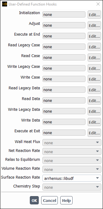
After you have interpreted (Interpreting UDFs) or compiled (Compiling UDFs) your DEFINE_SR_RATE UDF, the name of the function you supplied as a DEFINE macro argument will become visible and selectable in the User-Defined Function Hooks dialog box (Figure 6.68: The User-Defined Function Hooks Dialog Box) in Ansys Fluent.
To hook the UDF to Ansys Fluent, first set up an appropriate reaction model in the Species Model dialog box.
Setup → Models → Species
Edit...
Select Species Transport from the Model list in the Species Model dialog box, and enable the Volumetric and Wall Surface options in the Reactions group box. Make sure that you do not use the Stiff Chemistry Solver (as the Chemistry Solver), and click .
Next, open the User-Defined Function Hooks dialog box (Figure 6.68: The User-Defined Function Hooks Dialog Box).
Parameters & Customization → User Defined Functions
Function Hooks...
Select the function name (for example, arrhenius::libudf) in the Surface Reaction Rate Function drop-down list in the User-Defined Function Hooks dialog box, and click .
See
DEFINE_SR_RATE
for details
about DEFINE_SR_RATE functions.
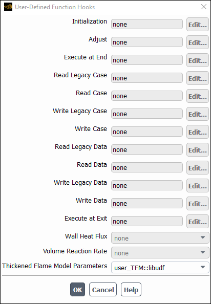
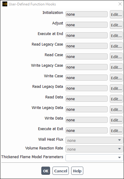
After you have interpreted (Interpreting UDFs) or compiled (Compiling UDFs) your DEFINE_THICKENED_FLAME_MODEL UDF, the name of the function you supplied as a DEFINE macro argument will become visible and selectable in the User-Defined Function Hooks dialog box (Figure 6.68: The User-Defined Function Hooks Dialog Box) in Ansys Fluent.
To hook the UDF to Ansys Fluent, select Species Transport with Volumetric Reactions enabled in the Species Model dialog box. Enable the Thickened Flame Model. Note that this option is only available for unsteady, laminar or LES/DES/SAS turbulent cases.
Setup → Models → Species
Edit...
Next, open the User-Defined Function Hooks dialog box (Figure 6.69: The User-Defined Function Hooks Dialog Box).
Parameters & Customization → User Defined Functions
Function Hooks...
Select the function name (for example, user_TFM::libudf) in the Thickened Flame Model Parameters drop-down list in the User-Defined Function Hooks dialog box, and click .
See
DEFINE_THICKENED_FLAME_MODEL
for details about DEFINE_THICKENED_FLAME_MODEL functions.
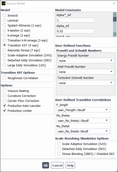
After you have interpreted (Interpreting UDFs) or compiled (Compiling UDFs) your DEFINE_TRANS UDF, the name of the function you supplied as a DEFINE macro argument will become visible and selectable in the Viscous Model dialog box in Ansys Fluent. To hook the UDF,
select Transition SST from the Model list in the Viscous Model dialog box (Figure 6.70: The Viscous Model Dialog Box).
Setup → Models → Viscous
Edit...
Next, select the function name (for example, user_Flength::libudf) from a drop-down list in the User-Defined Transition Correlations group box (for example, Flength), and click .
See
DEFINE_TRANS UDFs for details about DEFINE_TRANS functions.
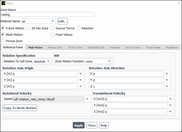
After you have interpreted (Interpreting UDFs) or compiled (Compiling UDFs) your
DEFINE_TRANSIENT_PROFILE UDF, the name of the function you
supplied as a DEFINE macro argument will become visible and
selectable in the Fluid or Solid dialog box (Figure 6.71: The Fluid Dialog Box) in Ansys Fluent, under the Reference
Frame tab, the Mesh Motion tab, and the Solid
Motion tab if the Frame Motion, Mesh
Motion, and Solid Motion options are enabled,
respectively.
Select the function name from a drop-down list in the Rotational Velocity or Translational Velocity group boxes in the Fluid or Solid dialog box, and click .
See
DEFINE_TRANSIENT_PROFILE
for
details about DEFINE_TRANSIENT_PROFILE functions.
After you have interpreted (Interpreting UDFs) or compiled (Compiling UDFs) your DEFINE_TURB_PREMIX_SOURCE UDF, the name of the function you supplied as a DEFINE macro argument will become visible and selectable in the User-Defined Function Hooks dialog box (Figure 6.72: The User-Defined Function Hooks Dialog Box) in Ansys Fluent.
To hook the UDF to Ansys Fluent, open the User-Defined Function Hooks dialog box (Figure 6.72: The User-Defined Function Hooks Dialog Box).
Parameters & Customization → User Defined Functions
Function Hooks...
Important: You must have a premixed combustion model enabled in the Species Model dialog box.
Select the function name (for example, turb_flame_src::libudf) in the Turbulent Premixed Source Function drop-down list in the User-Defined Function Hooks dialog box, and click .
See
DEFINE_TURB_PREMIX_SOURCE
for
details about DEFINE_TURB_PREMIX_SOURCE functions.
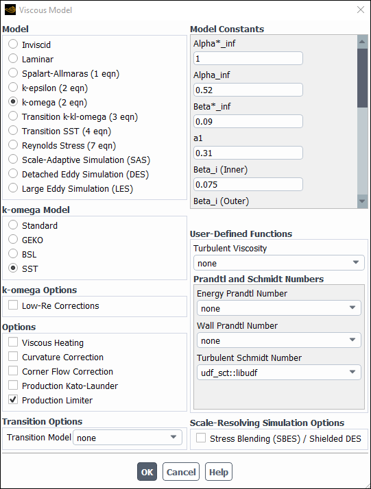
After you have interpreted (Interpreting UDFs) or compiled (Compiling UDFs) your DEFINE_TURB_SCHMIDT UDF, the name of the function you supplied as a DEFINE macro argument will become visible and selectable in the Viscous Model dialog box in Ansys Fluent. To hook the UDF,
first open the Viscous Model dialog box (Figure 6.73: The Viscous Model Dialog Box) and set up a turbulence model.
Important: If you select k-epsilon from the Model list, you must not select RNG from the k-epsilon Model list.
Setup → Models → Viscous
Edit...
Next, select the function name (for example, udf_sct::libudf) from the Turbulent Schmidt Number drop-down list under User-Defined Functions in the Viscous Model dialog box, and click .
Important: The Species Transport model must be selected in the Species Model dialog box for the Turbulent Schmidt Number drop-down list to be visible in the Viscous Model dialog box.
See
DEFINE_TURB_SCHMIDT UDF for details
about DEFINE_TURB_SCHMIDT functions.
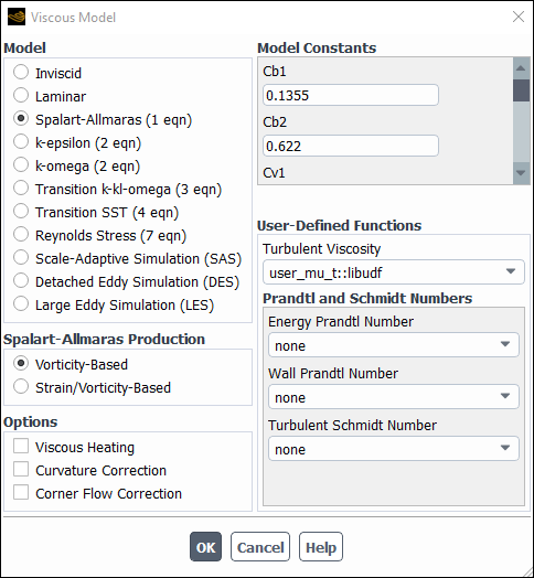
After you have interpreted (Interpreting UDFs) or compiled (Compiling UDFs) your DEFINE_TURBULENT_VISCOSITY UDF, the name of the function you supplied as a DEFINE macro argument will become visible and selectable in the Viscous Model dialog box (Figure 6.74: The Viscous Model Dialog Box) in Ansys Fluent.
Setup → Models → Viscous
Edit...
To hook the UDF to Ansys Fluent, select the function name (for example, user_mu_t::libudf) from the Turbulent Viscosity drop-down list under User-Defined Functions in the Viscous Model dialog box, and click .
See
DEFINE_TURBULENT_VISCOSITY
for
details about DEFINE_TURBULENT_VISCOSITY functions.
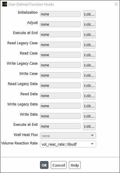
After you have interpreted (Interpreting UDFs) or compiled (Compiling UDFs) your DEFINE_VR_RATE UDF, the name of the function you supplied as a DEFINE macro argument will become visible and selectable in the User-Defined Function Hooks dialog box (Figure 6.75: The User-Defined Function Hooks Dialog
Box) in Ansys Fluent.
To hook the UDF to Ansys Fluent, first set up an appropriate reaction model in the Species Model dialog box.
Setup → Models → Species
Edit...
Select Species Transport from the Model list in the Species Model dialog box, and enable the Volumetric option in the Reactions group box. Make sure that Chemkin-CFD Solver is not selected as the Chemistry Solver, and click .
Next, open the User-Defined Function Hooks dialog box (Figure 6.75: The User-Defined Function Hooks Dialog Box).
Parameters & Customization → User Defined Functions
Function Hooks...
Select the function name (for example, vol_reac_rate::libudf) in the Volume Reaction Rate Function drop-down list in the User-Defined Function Hooks dialog box, and click .
See
DEFINE_VR_RATE
for details
about DEFINE_VR_RATE functions.
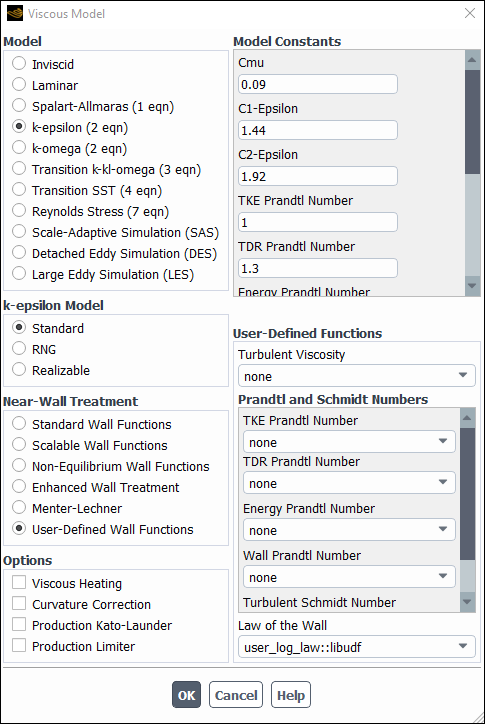
After you have interpreted (Interpreting UDFs) or compiled (Compiling UDFs) your DEFINE_WALL_FUNCTIONS UDF, the name of the function you supplied as a DEFINE macro argument will become visible and selectable in the Viscous Model dialog box (Figure 6.76: The Viscous Model Dialog Box) in Ansys Fluent.
Setup → Models → Viscous
Edit...
To hook the UDF, select k-epsilon from the Model list in the Viscous Model dialog box, and select User-Defined Wall Functions from the Near-Wall Treatment list. Then, select the function name (for example, user_log_law::libudf) from the Law of the Wall drop-down list, and click .
See
DEFINE_WALL_FUNCTIONS
for
details about DEFINE_WALL_FUNCTIONS functions
in Ansys Fluent.
After you have interpreted (Interpreting UDFs) or compiled
(Compiling UDFs) your
DEFINE_SOURCE_FE UDF, the name of the function you supplied as a
DEFINE macro argument will become visible and selectable when
defining displacement source terms for solid cell zones in Ansys Fluent.
To hook the UDF to Ansys Fluent, first select the Linear Elasticity model in the Structural Model dialog box.
Setup → Models →
Structure
Edit...
Next, open the Cell Zones task page.
Setup →
![]() Cell
Zones
Cell
Zones
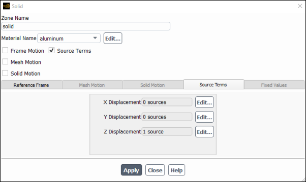
Select a solid zone in the Zone list and click Edit... to open the Solid dialog box (Figure 6.77: The Solid Dialog Box).
In the Source Terms tab, select an appropriate directional displacement (such as Z Displacement) and click Edit... to open, for example, the Z Displacement source dialog box.
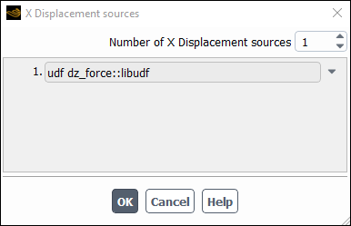
Increase the Number of Z Displacement sources and hook the UDF by, for example selecting the function name (udf dz_force) from the drop-down list.
See
DEFINE_SOURCE_FE
for details about
DEFINE_SOURCE_FE function in Ansys Fluent.
After you have interpreted (Interpreting UDFs) or compiled (Compiling UDFs) your DEFINE_WSGGM_ABS_COEFF UDF, the name of the function you supplied as a DEFINE macro argument will become visible and selectable in the Create/Edit Materials dialog box in Ansys Fluent.
To hook the UDF to Ansys Fluent, first make sure that you have selected a radiation model from the Model list of the Radiation Model dialog box and have set up a species transport or soot formation model. Then open the Materials task page.
Setup →
![]() Materials
Materials
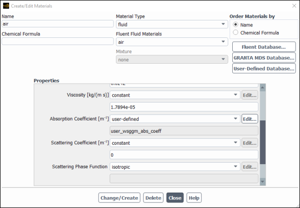
Select the mixture in the Materials list and click the Create/Edit... button to open the Create/Edit Materials dialog box (Figure 6.79: The Create/Edit Materials Dialog Box).
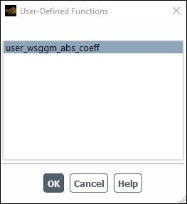
Next, select user-defined-wsggm from the Absorption Coefficient drop-down list in the Properties list, which opens the User-Defined Functions dialog box (Figure 6.80: The User-Defined Functions Dialog Box).
Select the function name (for example, user_wsggm_abs_coeff::libudf) from the list of UDFs displayed in the User-Defined Functions dialog box and click . The function name will then be displayed in a field under the Absorption Coefficient drop-down list in the Create/Edit Materials dialog box. Finally, click Change/Create in the Create/Edit Materials dialog box to save the settings.
See
DEFINE_WSGGM_ABS_COEFF
for
details about DEFINE_WSGGM_ABS_COEFF functions,
and Inputs for a Composition-Dependent Absorption Coefficient in the User's Guide for further information about inputs for composition-dependent absorption
coefficients.
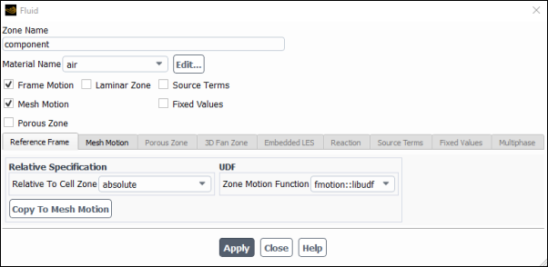
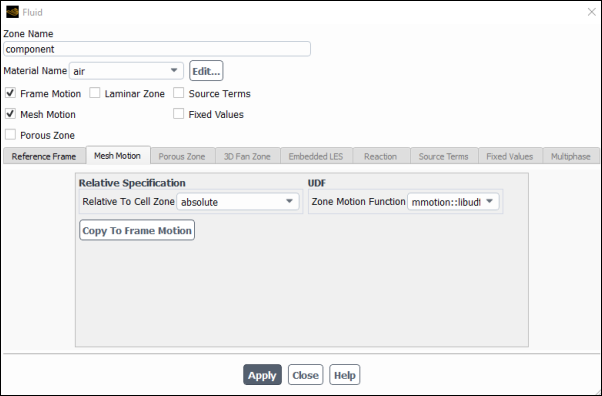
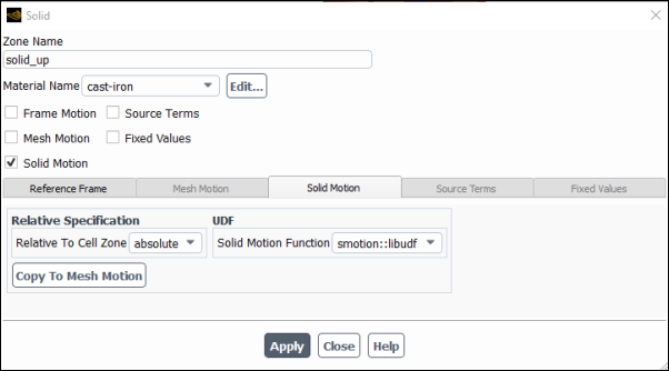
After you have interpreted (Interpreting UDFs) or compiled
(Compiling UDFs) your
DEFINE_ZONE_MOTION UDF, the name of the function you supplied as a
DEFINE macro argument will become visible and selectable in the
Fluid or Solid dialog boxes in Ansys Fluent, under the
Reference Frame tab, the Mesh Motion tab, and the
Solid Motion tab if the Frame Motion,
Mesh Motion, and Solid Motion options are enabled,
respectively.
Setup →
![]() Cell Zone
Conditions
Cell Zone
Conditions
Select the fluid or solid zone and click the Edit... button to open the Fluid or Solid dialog box.
Next, select the UDF from the Zone Motion Function drop-down list in the Fluid dialog box or the Zone Motion Function or Solid Motion Function drop-down list in the Solid dialog box.
See DEFINE_ZONE_MOTION
for details about
DEFINE_ZONE_MOTION functions.


