


This section presents a list of common problems that may be encountered when using OptiGrid. Each problem description is followed by one or more possible actions which may help to overcome the problem.
Problem: OptiGrid did not complete the adaptation.
In order to figure out what happened, first look at the error log file. If the process ended abnormally, there should be a message in this file indicating what the problem is.
The following are examples of the most commonly encountered error messages:
Error: variable name, *variable* was not found in the solution file.
In this message, *variable* can be any of the solver labels that were selected under the variable for adaptation. The message indicates that the solver label from the solution file was entered incorrectly. To see a list of the solver labels for the variables in the solution file, use the edit variable labels or refresh the list.
Error: can't open result interface.
OptiGrid was not able to read the input solution file. Check the solution file format and filename.
Error: OptiGrid found more than 100 layers of prisms in the domain. Stop.
The maximum number of layers of prisms is 100. Either generate a new mesh with fewer layers or contact FENSAP-ICE support for a customized version of OptiGrid.
Error: Periodic nodes were detected in the mesh, but periodicity is not defined in the geometry file.
OptiGrid detected periodicity in the mesh but not in the geometry file. Periodicity must be properly defined to allow OptiGrid to project these nodes correctly. Update the mesh or the geometry.
Error: The Y+ correction parameters for certain groups of adjoining surface families are incompatible. Curves and bars must be created at the junction between the following groups of families: WING_TOP WING_BOTTOM. Adaptation cannot proceed. Stop.
The parameters for Y+ adaptation must be consistent across surfaces that touch one another. Correct the configuration file to specify valid parameters.
Error: OptiGrid execution aborted unexpectedly. Check the error.user file.
This is a general error message. Detailed information to be found in error.user (or error.user.xxx in MPI mode where xxx is the processor ID).
Error: Movement 2: edge is too long 453.
Refine 12: new edge is too small 286.
Collapse 23: failed conformity check on elements 102539.
Swap 26: no best swap found 45873.
At the end of the adaptation, OptiGrid reports the number of rejected operations by occurrences. There are messages for node movement, refinement, coarsening, and swapping. A brief message describes each operation, followed by the number of times this operation was rejected. Some rejections occur naturally. However, a high count on some operations (for example edge is too long or edge is too small) can reveal mesh constraints that are too severe.
Problem: OptiGrid did not adapt everywhere in a regular fashion.
Action 1:
OptiGrid adapted in some regions, but not in others. Verify if the maximum # nodes or elements was reached during the course of the adaptation. This information can be found on the control window. If either maximum is reached, refinement and swapping is halted until elements and nodes are freed through coarsening. This prevents OptiGrid from adapting evenly throughout the domain. To avoid this problem, increase the maximum # nodes and elements parameters accordingly.
Action 2:
The adaptation may be incomplete. It is possible that OptiGrid has not converged, in which case the main iterations must be increased. Also, try increasing the number of node movement pre- and post-iterations, and maximum edge swapping iterations. To get an idea of how well the adaptation process has converged, look at the control window under edge convergence. If the percentage of edges operated on steadily decreases from iteration to iteration until it is around 1%, this is a good indication that the adaptation process has converged properly. However, more iterations of node movement may still be required.
Action 3:
It is difficult to adapt in columns of prisms. Thin layers of prisms are sensitive to the aspect ratio and warpage. It is also difficult to rapidly increase the height of prisms. Under-relaxation on node movement is suggested.
Action 4:
The presence of pyramid transition elements between tetras and hexas or prisms will limit the adaptation operations in the neighboring tetras. Pyramids should be avoided.
Problem: The adapted mesh is too coarse.
Action 1:
The target error density is too high. If the adaptation was done using the user-specified option, then the target error density must be lowered. If the adaptation was done using the target # elements or nodes, then you must increase the target # elements or nodes accordingly. Remember to increase the maximum number of elements and the nodes to a value which is at least 20% greater than the target number, otherwise the adaptation process will not be properly completed. As a general rule, for tetrahedral elements, the number of elements is 5 to 6 times greater than the number of nodes.
Action 2:
The minimum edge length may be too large, causing too much coarsening.
Problem: The adapted mesh is too dense.
Action 1:
The target error density is too low. If the adaptation was done using the user-specified option then the target error density must be increased. If the adaptation was done using the target # elements or nodes, then you must decrease the target # elements or nodes accordingly. You may also increase the minimum edge length to prevent the creation of very small elements.
Action 2:
The maximum edge length may be too small, causing excessive refinement in the far-field.
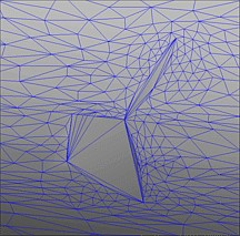
Problem: There are asperities on rounded surfaces.
Surface asperities are defined as edges carving through a rounded surface, leading to sharp angles between adjacent faces and causing a kink in the surface (See figure below).
Action 1:
The original mesh is too coarse near rounded surfaces. Refine the mesh in those regions and restart the adaptation.
Action 2:
The parameter for maximum coarsening on curvature is too small. Although a small value is preferable in order to better represent the curvature of the surface, you may have to start from a higher value (for example 0.10) and gradually decrease it over several adaptation cycles. When there are faces that are too coarse to properly represent curved surfaces, it is advised that you refine the worst edges first and then proceed to refine slightly better edges, rather than refining all these edges at once. This can be accomplished by first running OptiGrid with a high value for the maximum coarsening on curvature, and then progressively lowering the value from cycle to cycle.
Problem: There are clusters (patches) of elements on surfaces.
There may be fluctuations in the solution which lead to a high error estimation and high refinement in certain regions. Check that the solution is smooth and not patchy and that there are no hot spots. If there are such fluctuations, the solution must be rerun or continued until it is more fully converged. It is also possible to apply data filtering on the adaptation variable using the OptiGrid filter (See Error Computation).
Problem: The height of prisms is not uniform or the prisms are not orthogonal to the surface.
Action 1:
The minimum edge length may be too large, causing OptiGrid to fail to achieve the desired Y+. Lower this value.
Action 2:
The aspect ratio and warpage of prisms may be too restrictive. Lower these values.
Action 3:
Node movement may be incomplete. Try to increase the number of node movement iterations or decrease the relaxation factor for displacement.
Action 4:
If the bad prisms are near the trailing edge of a wing, there is not much that can be done since the normal vector to the surface cannot be evaluated accurately at a sharp corner. In such a case, make sure that the initial mesh is suitable for the solver in that region.
Action 5:
There can be pyramids between layers of prisms and tetrahedral elements, preventing proper adaptation. In this case, it would have been preferable to eliminate the pyramids during the mesh generation phase.
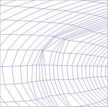
Problem: Hexahedral elements look pinched on the surface.
The next figure shows an example of pinched elements in a hexahedral mesh.
Action:
There are surface nodes which are not moving, making the grid look pinched near these nodes. Node movement is more delicate for hexas. Try decreasing the relaxation factor for displacement and the minimum face angle parameters. Decreasing the minimum face angle will not necessarily lead to skewed elements, but it will allow node movement to succeed if at some transitory state the face angle is below this threshold. Similarly, the values for the minimum hexahedral determinant and the minimum hexahedral warpage can be lowered to allow more freedom in the movement of nodes, but this may lead to slightly more distorted cells. Adjusting the error density can also affect the outcome of node movement for hexas (and other element types as well).
Problem: There is little difference between the initial hexahedral mesh and the adapted mesh.
Action:
Node movement depends on the target error density and choosing a target error density that is too high may prevent movement of the nodes if the error of the initial mesh is already smaller than the specified target. In most cases, using the automatic error estimator should work. If not, you should plot the error distribution using view error and select a suitable value.
Problem: The Minimum/Maximum edge length settings are not respected.
Action:
The length of any edge should remain between these bounds. OptiGrid will never create edges that violate these constraints. If these limits are not respected in the original mesh, OptiGrid may not be able to fix these edges, but it will not make them worse. If this is a major concern, try running more main iterations and the problem should go away on its own.
Problem: The Minimum aspect ratio is not respected.
Action:
If the original mesh contains elements whose aspect ratio is below the specified minimum aspect ratio, OptiGrid may or may not be able to eliminate them. As for the edge length constraint, the aspect ratio constraint is strictly enforced in OptiGrid, meaning that no new element violating this constraint will be introduced.
Problem: The solver does not converge when an attempt is made to restart the solution on the adapted mesh.
Action 1:
OptiGrid writes out the solution fields interpolated on the new adapted mesh. It is strongly recommended that the solver be restarted using this interpolated solution.
Action 2:
The mesh may have areas where patches of excessively small elements were created next to very large elements. This kind of element cluster can prevent a solver from converging properly or give unrealistic solutions. It is necessary to locally repair these patches of small elements - they are likely due to problems with the CAD data.
Action 3:
The solver may have difficulty converging because the adapted mesh is too anisotropic. This is more likely to be the case with finite volume codes. Increase the minimum tetra aspect ratio and the minimum prism aspect ratio, if applicable. A value of 0.25 for the mesh degree of anisotropy is a safe first guess.
Action 4:
The wrong adaptation variable might have been used. For example, adapting a grid for a viscous flow based on pressure will coarsen the mesh in the boundary layer, making the new grid unsuitable to viscous flow calculations, therefore leading to poor convergence of the flow solver. Simply restart the adaptation using an appropriate flow variable.