


The primary particle flow computations do not account for the fact that some particles, such as ice crystals and large droplets, can bounce off a surface and re-enter the flow. Crystals bounce off engine components such as the shroud, nose-cone, splitter and the blades. The amount of bouncing crystals can be significant and this is the mechanism that enables them to travel deep inside the compressor core.
Likewise, water film can spray from rotating components such as the spinner, hub and blades and re-join the flow. The particle reinjection options have been included to allow the modeling of these phenomena.
The activation of Particle reinjection enables ICE3D-TURBO options for each component within the DROP3D-TURBO configuration panels. A review of the ICE3D-TURBO options listed in Ice Accretion in Turbomachines is highly recommended before configuring the re-injection models.
This option is available in the Particle reinjection menu of the Model panel of the DROP3D-TURBO configuration.

The option determines the concentration of ejected particles and transfers it to the exit plane of a component without the calculation of particle trajectories. Icing parameters must be set when this option is activated. Only icing-activated wall boundaries will re-inject particles into the flow.
This feature is computationally expensive but provides a more accurate representation of the crystal and film reinjection dynamics in a component. The option is available in the Particle reinjection list of the Model panel of a DROP3D-TURBO run. Like the Simple reinjection option, icing parameters need to be set up when this option is activated.

The Complete model uses the reinjected particle concentrations, velocities and temperatures generated from an automated ICE3D-TURBO run to write a boundary condition file to treat wall boundaries as inlets.
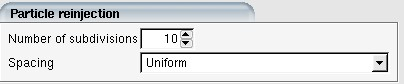
When the particle detachment zones are determined in ICE3D-TURBO, a second DROP3D-TURBO run on the same component establishes the secondary particle trajectories from the wall to the exit. The re-injecting wall boundaries are divided into several sub-sections. The Number of subdivisions controls number of subsections that are divided in the axial direction. The default number of split sections is set to 21. More subdivisions would increase the accuracy of the solution but can be computationally expensive. The Spacing defines the type of spacing between subsections. Currently, only a uniform spacing is available.
Note: If you are trying to simulate reinjection due to bouncing crystals, ensure that either the NTI Bouncing Model or NRC Bouncing Model is enabled. If you are trying to simulate film shedding due to centrifugal force on moving components, the Beading model must be activated to ensure that the critical bead height for detachment can be established.