


The following sections illustrate the settings required to run a dry-air simulation.
The input parameters and grid files of all fluid and solid domains should be assigned before starting the CHT3D calculation.
For the fluid domain,
When FENSAP has been selected as the Flow solver in the CHT configuration window, the graphical interface opens the FENSAP input parameter window. Consult FENSAP - Flow Solution of this manual for guidelines on how to set up the input parameters for the airflow calculation.
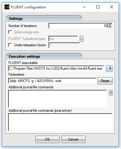
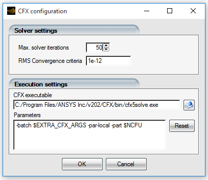
When Fluent or CFX has been selected as the Flow solver, the external and internal flow settings can be adjusted by clicking the config icon of fluid_ext and fluid_int. The new input will overwrite some of the original Fluent or CFX settings such as solver iterations and convergence criteria. The execution settings include the path of the executable file, run parameters, and additional commands if required. Guidelines to properly set Fluent and CFX simulations within FENSAP-ICE are provided in Multishot with Fluent and Multishot with CFX. It is advisable to consult the Ansys FENSAP-ICE Tutorial Guide for examples on how to set-up these CHT calculations using Fluent and CFX as flow solvers.
For the solid domain, the graphical interface opens the C3D input parameter window. More information on input parameters for the heat conduction calculation can be found in C3D - Unsteady Heat Conduction.
Tip: Since CHT3D is an iterative process, a limited number of iterations should be performed on the fluid and solid domains at each CHT3D iteration. The maximum number of time steps in FENSAP, Fluent and CFX should be set in the range 20 - 50 in order not to spend an unnecessary amount of time in the CHT iteration.
To reduce computational time, both the flow solver and C3D should be configured to write their solution files only at the end of their respective calculations.
In C3D, which is an unsteady solver, the Total time setting is what really controls the convergence and stability of CHT3D. It acts as the global time step of the simulation. Larger values may cause oscillating minimum/maximum solid temperatures between CHT3D iterations since the conduction process in the solid can advance more rapidly than the other solution modules (flow, icing). A low value, between 1 - 5 seconds, is recommended for this setting. Smaller geometries will require smaller time increments for stability. For every problem type, it is recommended studying the case behavior with respect to time integration settings before starting a large campaign of simulations. Similar to any other time-marching solver, lower time step values will require more iterations for global convergence.
The CHT3D iterative process starts with initial airflow solutions computed for each fluid domain. To assign these initial solutions, right-click the corresponding icons, select from the menu and browse to assign the appropriate files. Alternately, the configuration files of the initial solutions can be dragged & dropped onto the corresponding sub-run configuration files.