


The window shown below will appear when a CHT3D run is created.
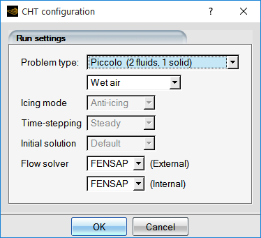
The Problem type menu offers a choice of or anti-icing options.
The flow regime, , or should be selected next. In the regime, CHT3D iteratively transfers the interface conditions (wall heat fluxes and temperature) among the fluids and the solid domains. Other supported flow solvers, such as Fluent and CFX, can be selected with the Flow solver pull-down menu.
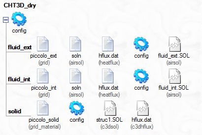
Click the button to create the CHT3D run. The following figure shows the configuration of a typical dry-air steady-state anti-icing simulation. Each row in the figure corresponds to a domain.
In the regime, intended for steady-state anti-icing calculations, CHT3D iteratively transfers the interface conditions (wall heat flux and temperature) between the different fluids and the solid domain interfaces, but also accounts for the water impingement and the surface water film energy balance on the external surface of the metal skin.
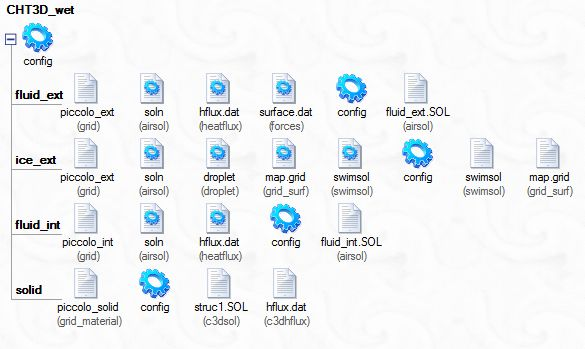
Note: An extra row for the ICE3D run appears in this wet-air setup. ICE3D will compute the water film flow on all wall surfaces as a balance of incoming water, evaporation/ sublimation, convection and phase-change driven by heat flux exchanges between domains.
Important: Only the thickness and extent of the water film on the surface is meaningful. Any ice shape produced by ICE3D in this type of CHT3D computation is not representative of a real ice shape, since the ice mass and ice thickness are reset at each CHT iteration.
Note: There is no sub-run for the water droplet solution, since the incoming water flow rate remains unchanged during the solution process. The DROP3D solution must be computed in advance and used for the initial and CHT3D ICE3D runs.
The fluid_ext and fluid_int, as well as the ice_ext sub-runs, are configured as restarts. An initial solution must be run for each fluid domain including its water film solution separately before starting the CHT3D procedure. These solutions must be then supplied to the corresponding CHT3D sub-run as a restart file.
The initial ICE3D run (30-40 sec only) is required to establish a film of water on the surface and to provide a meaningful starting point that accelerates CHT3D convergence. For smaller aircraft components, like engine guide vanes and struts, air data probes, etc, a much shorter duration of the initial icing run, around 5 seconds, should be sufficient. More details can be found in Ansys FENSAP-ICE Tutorial Guide in the Ansys FENSAP-ICE Tutorial Guide.
The initial temperature solution on the air flow surfaces, whether isothermal or adiabatic, will change with the CHT process and reach a new equilibrium.
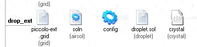
In the Wet-air & droplets regime, CHT3D iteratively transfers the interface conditions (wall heat flux and temperature) across the fluids and solid domain interfaces and accounts for the water impingement and the surface water film energy balance on the external surface. It also transfers the temperatures of the airflow domain to the droplet domain, solving an energy balance in the droplet domain which contributes to the heating or cooling of droplets. In such a run, there will be a drop_ext input line, containing the droplet configuration.
The configuration file in each row controls the behavior of the corresponding solver, while the main configuration icon controls the behavior of the coupling algorithm. It is important to note that the reference conditions of the initial solutions must be exactly the same as those specified in the configuration files of the sub-runs, otherwise the calculation will converge to erroneous values. The easiest way to avoid mistakes is to drag & drop the configuration files of the initial solutions onto the configuration files of the corresponding CHT3D sub-runs. This regime is supported by FENSAP, Fluent and CFX.
In the or regimes, steady-state CHT3D computations can be performed for piccolo tubes and electro-thermal systems in mode. In electro-thermal simulations, the mode is also available. This mode enables unsteady CHT3D computations through the solid, the melting/accreting ice layer and the water film. The current modeling process requires a wet-air de-icing simulation to start on a surface which is free of ice. Therefore, the Initial solution is always set to From DRY and ice needs to accrete during the CHT simulation before de-icing it.