The wet-air regime requires a more complex setup than dry-air.
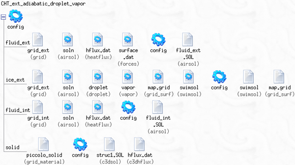
The input parameters and grid files of all fluid and solid domains should be assigned before starting the CHT3D calculation. Refer to FENSAP - Flow Solution, Recommendations to Set up a Fluent Calculation, Recommendations to Set up a CFX Calculation, DROP3D - Droplet and Ice Crystal Impingement, ICE3D - Ice Accretion and Water Runback, C3D - Unsteady Heat Conduction for the input parameters required for FENSAP, Fluent, CFX, DROP3D, ICE3D and C3D, respectively.
In this flow regime, both water impingement (DROP3D) and water runback and evaporation (ICE3D) on the external skin are considered. For all anti-icing and de-icing simulations, the water impingement solution remains constant in time, therefore the ice growth should not be allowed to increase excessively. For ICE3D, the mass and energy equations for the film of water are solved by considering the convective (FENSAP, Fluent or CFX) and anti-icing (C3D) heat fluxes.
Tip: Anti-icing simulations drive the inter-domain thermodynamic balance towards a steady-state solution. In ICE3D, which is an unsteady solver, the time duration should be set to a small value, for example 10 to 40 seconds, sufficient for the film to develop properly and for the temperature to converge. The Icing model should be set to .
The C3D Total time acts as the global time step for CHT3D iterations. Lower values improve convergence and stability while larger values reduce the total number of CHT3D iterations required for convergence. By default, a total time of 5 seconds is set. If minimum and maximum solid temperatures show oscillations between CHT3D iterations, this value can be reduced to 1 second, or even lower, depending on the problem.
Before the CHT3D iterative process can begin, initial airflow solutions must be computed on the corresponding internal and external flow grids. These initial solutions can then be used to start the CHT3D procedure. Right-click each of the input file icons on the left of the configuration icon, select from the menu and browse to assign the air solutions.
Tip: Initial external flow solutions computed for de-icing simulations should include the surface roughness generated during ice accretion. For anti-icing computations, clean surfaces can be used since they are expected to remain free of ice. In this case you should activate the transition model for the external airflow calculation.
Initial external flow solutions for anti-icing simulations should be computed with uncontaminated surfaces (no roughness), since they are expected to remain free of ice. In this case it is also strongly recommended to activate the transition model, since flow transition has a very noticeable impact on the accuracy of the simulation.
The CHT3D iterative process for the wet-air regime starts with an initial droplet solution, pre-computed on the external fluid domain. To assign this initial droplet solution to the ICE3D domain, right-click the corresponding icon, select and browse to assign the appropriate droplet solution file.
Tip: To quickly set up a CHT run, drag and drop the configuration icon of each initial run onto the configuration icon of the corresponding domain in the CHT run. FENSAP-ICE will automatically copy the parameters and will assign the solution files of the initial run to the input files of the CHT run. Remember to adjust the ICE3D and C3D total simulation time and the number of iterations in flow solver.
In engine icing simulations, performed as internal flow simulations, the inlet air temperature and the main reference temperature can be different. The isothermal temperature that is applied on the walls of crowded turbo passages will change the flow thermodynamics considerably. For these reasons, it is comment to conduct such simulations with adiabatic walls. When walls are set as adiabatic, the heat transfer coefficients required by ICE3D are computed using an alternative post processing approach, which is called Extended Icing Data (EID). The CHT algorithm is extended to support initial air solutions obtained in this manner and avoid duplication of work by rerunning with isothermal walls which is the classical CHT method. Furthermore, evaporative heat fluxes are the most important heat exchange terms for glaze ice and anti-icing models. Using an accurate surface vapor pressure distribution in calculation of these fluxes are important. It is recommended using the vapor transport model in addition to adiabatic walls and EID when conducting IPS simulations in internal passages and engine components.
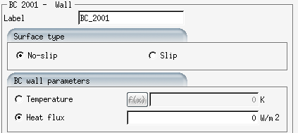
When configuring the external airflow simulation, set the walls adiabatic by
setting heat flux to 0:
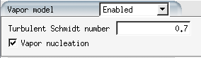
When configuring DROP3D for external domain, enable the vapor transport model:
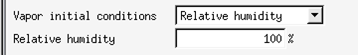
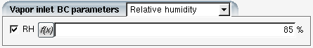
Vapor solution also requires the initial vapor concentration to be specified, which could be done in the form of relative humidity, wet bulb temperature, or vapor concentration. When using the relative humidity option, the local air temperatures will be used for the saturation vapor pressure calculations:
In the DROP3D boundary conditions, vapor information needs to be specified as well. This value will likely be different for multiple inlets in the computational domain:
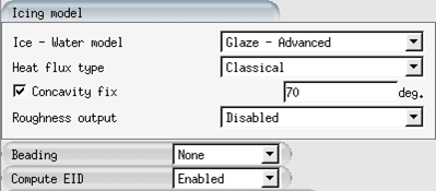
When configuring the initial ICE3D solution, enable Compute EID in the Icing model panel:
Starting with FENSAP-ICE version 24R2, the vapor solution fields are also stored in the droplet files to simplify post processing. Specifying a vapor solution file in the ICE3D configuration is no longer required, but maintained as for backward compatibility when using older droplet files without the vapor data.
The final CHT run will show the vapor solution icon as one of the inputs for the icing component: