In this section you will modify edge detection settings, set up filtering and add groups of edges.
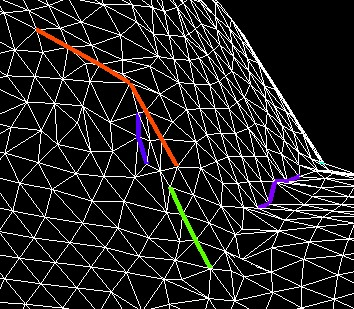
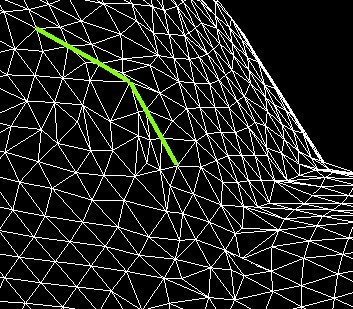
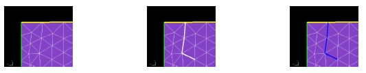
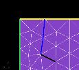
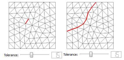
Consider the example shown below of one element junction with different angles on both sides. Here, one angle is detected with the default tolerance (edge in blue), while the other is not. In such case, it is necessary to change the default tolerance.

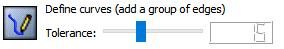
The auto-detection procedure uses default tolerances which are optimal for most grids. The tolerances button gives access to the detection thresholds dialog box where values can be better tuned for a specific grid.
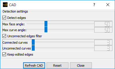
enables edge detection. If disabled, only the edges provided in the initial grid are used to reconstruct the geometry.
Max face angle adds edges whenever the angle between two surfaces is greater than the specified value. A lower value detects more edges, but may create undesired edges especially when the grid is too coarse to represent the geometry.
Max curve angle adds prescribed points onto curves if the angle is less than the input value. The edge is then split in two and a prescribed node is introduced at the breaking point.
If is selected, the selected tolerances will not erase edges added manually using the edition tools.
Unselect and to apply a full reset, and only consider edges provided by the input grid.
The icon performs the edge detection operation and refreshes the display.
sets the detection thresholds to their default values.
The option enables a filter to remove automatically most of CAD detection artifacts. These artifacts are small isolated edges not related to the geometry.
Unconnected curves is an orphan curve created during the detection process, which is not connected to any other curves at its end points. The curve is erased if its length is less or equal to the specified value.
Connected curves. Same as standalone curve, but the curve is connected to another curve at only one of its ends. The curve is erased if its length is less or equal to the specified value.
The edge filter is applied on detected edges only and will not remove user-created curves.
The activation of this tool allows adding and removing edges manually by a right-mouse clicking the edge in the 3D window. Added edges are shown in white, while removed edges are in black:
Use Refresh CAD to commit the current modification and refresh the edge colors.

Tip: Undo and redo any edition operations with Edit → Undo/Redo or Ctrl+Z/Ctrl+Shift+Z. However, mandatory edges obtained from the grid (boundary condition patches, BAR elements, etc.) will not be removed by this operation.
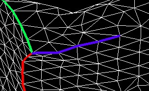
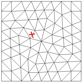
This tool allows adding a group of interconnected edges by clicking only one edge of this group. The edges are then connected one by one, if the connected edge is nearly parallel to the current one.
Transfer to selection mode:
and right-mouse click in the 3D window to add edges.
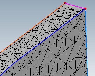
For example, the edges of this cube could be added manually, instead of using the auto-detection tool.
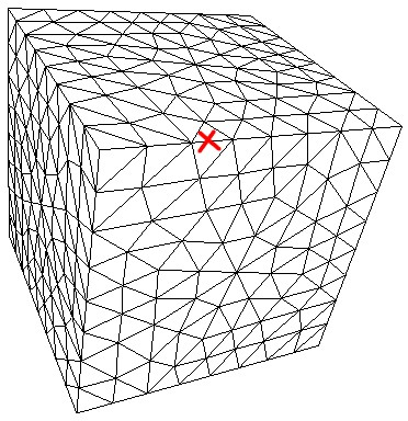
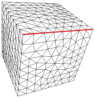
Figure 13.10: The Group of Edges Detected Is Shown in Red. Parallel Edges Connected to the Initial Edge Were Selected Automatically
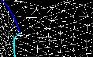
Prescribed points are separations between edges. Edges can be split in two by adding a prescribed point at a given position, or joined together by removing the prescribed point.
While the edit curve breaks tool is active, existing prescribed points are shown
with red dots. Transfer to selection mode ![]() and right-mouse click a node position to add and remove this
point. New prescribed points are shown in white, while removed ones are in
black.
and right-mouse click a node position to add and remove this
point. New prescribed points are shown in white, while removed ones are in
black.

When this tool is active, right-mouse click an edge to delete it. However some mandatory curves cannot be deleted.