


In this section, you will reconstruct a CAD surface, view the reconstructed CAD and save your geometry file.
OptiGrid reconstructs the CAD surfaces from an input grid, and writes three files required for mesh adaptation:
gridFilename.geom → geometry (CAD).
gridFilename.enti → zones.
gridFilename.info → grid-to-CAD conversion.
These 3 files are saved in the same directory as the input grid. The first two may be moved to other locations, if needed, however the grid-to-CAD conversion file must stay in the same directory as the grid.
When performing mesh adaptation, OptiGrid writes the following two files:
gridFilename_adapted → the adapted grid.
gridFilename_adapted.info → the adapted grid-to-CAD conversion file.
This new grid-to-CAD conversion file enables the adapted grid to be used with the original CAD. The CAD generation step can therefore be performed only once, before the first adaptation sequence.
When starting CAD reconstruction, the first step consists in reading the input grid. The basic features of the CAD are then detected: external surfaces, internal boundaries between volume elements, automatic edges, and other geometric features.
For large-size grids and slow computers, this operation may take some time as it is the most demanding part of the process, in both RAM usage and CPU time.
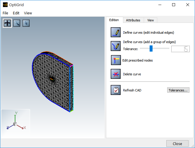
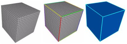
The edition mode shows the grid in wire frame and edges with bold colored lines.
Mesh edges are colored lines or splines separating surfaces in the CAD. They are groups of concatenated mesh segments. These edges should separate the CAD surfaces at natural borderlines, geometric features or boundary conditions zones borders.
Auto-detection uses a specific threshold to detect edges. The tolerance modifies these thresholds.
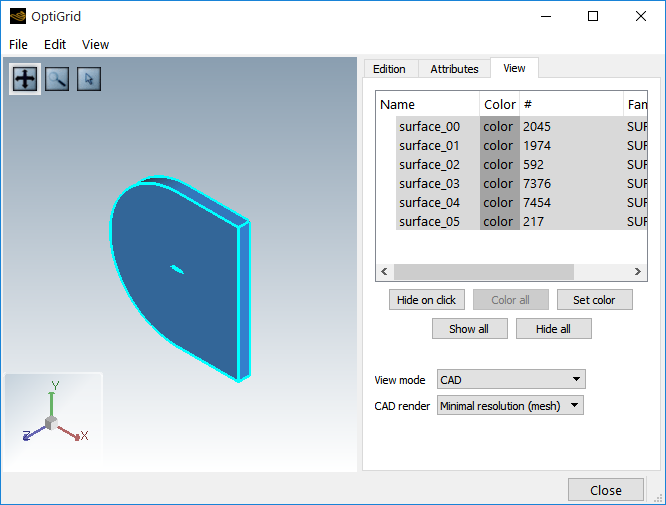
Each mesh surface is converted to a CAD surface and its curvature is deduced from the mesh topology. CAD surfaces are made of parametric surfaces and splines. The CAD can be displayed by selecting View mode → .
The CAD is displayed in blue, with its edges in lighter blue. By default, the CAD is drawn using the same resolution as the grid (1 triangle per grid face). The CAD is however a high-order representation of a grid topology. The resolution of the display can be improved by increasing the graphical detail settings, as in the example shown below. An increased resolution requires, however, more RAM for large grids and, therefore, reduces the graphical rendering speed.
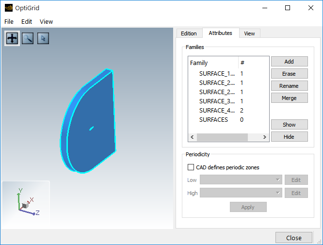
A group of surfaces can be flagged as a family for mesh adaptation, for example, to impose y+ constraints. Families cannot overlap and are displayed in red.
Families are listed under the attributes tab. When editing a grid in FENSAP or Fluent formats, families are automatically created to fit the boundary condition zones.
New families can be created using . Use short and simple identifier names for groups and families, with alphanumerical and underscore characters only. Other operations (, and ) are also available.
Transfer to selection mode ![]() and right-mouse click the 3D window to add or remove surfaces
to or from the selected family. All surfaces removed from one family are added to
the default SURFACES family. The SURFACES
family contains all surfaces not owned by any other family.
and right-mouse click the 3D window to add or remove surfaces
to or from the selected family. All surfaces removed from one family are added to
the default SURFACES family. The SURFACES
family contains all surfaces not owned by any other family.
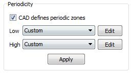
Some grid formats (for example FENSAP, Fluent) already define the periodicity between different boundary patches. This information is saved in the geometry file, and used by OptiGrid for mesh adaptation.
If the grid file does not provide such information, it may be added to the geometry file within OptiGrid. For this, select two families between which periodicity should be imposed (edit and click two surfaces). Configure sets the detection thresholds and validates the periodicity between the two surface groups. If the periodicity is invalid, a warning message is issued when saving the CAD and, consequently, the periodicity will not be saved in the geometry file.