The following topics are included in this section:
The Part Quick Action icons can be used to quickly set for parts. To use these controls:
Select the desired part(s) in the Parts list.
Click appropriate icon to set the desired attribute:

Part Visibility 
Color, Lighting, Set Transparency 
Line Width 
Visibility Per Viewport 
Change the Visual Representation 
Displacement 
Visual Symmetry 
Display Labels 
Node Representation 
Filter Elements 
Element Blanking 
Shading Type 
Hidden Line 
Set Auxiliary Clipping 
Set Global Viewing Parameters
For model parts, the Creation section in the Feature Edit dialog allows improved boundary mesh option, scaling, and filtering of elements. For structured model parts, you can change the model part I/J/K range.
Right click on the model part name in the Parts list and choose or right click on the model part in the graphics window and choose , or double click the model part in the Parts list.
By default, any changes you make to will take effect immediately. If you wish to “batch” a series of changes turn on the toggle at the bottom of the dialog. When you are ready to apply a set of changes click the button.
Open the Creation turndown, then set the desired attribute(s):

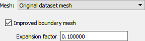
A Model Part can be remeshed in 2D or in 3D or projected onto one of 3 orthogonal planes using an improved boundary mesh option and a variable expansion factor. See Model Parts.
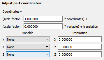
A Model Part can be rescaled and translated independently in the X, Y and Z directions.
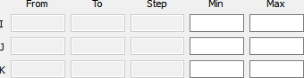
A Structured Model Part can have the I/J/K Range changed.
A Model Part’s elements can be filtered (up to six filters) by a variable or a value. See Filter Part Elements.
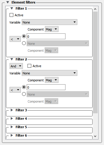
See Model Parts and Filter Part Elements.
The General section in the Feature Edit dialog duplicates many of the controls available in the part Quick Action Icon Bar. To set using the General section:
Right click on the part name in the Parts list and choose or right click on the part in the graphics window and choose , or double click the part in the Parts list.
OR Select → .
By default, any changes you make to will take effect immediately. If you wish to “batch” a series of changes turn on the toggle at the bottom of the dialog. When you are ready to apply a set of changes click the button.
Toggle the Toggle in the top right corner of the dialog to see the additional turndowns besides Creation.
Open the General turndown, then set the desired attribute(s):
Toggle Part Visibility
Toggle auxiliary clipping on/off (Set Auxiliary Clipping).

Toggle whether the client’s portion of the part changes if the current time step changes.

Set color by constant or color by variable (Change Color).
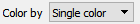
Set the part color if constant.

Toggle part hidden surface
Toggle part hidden line

Set part shading parameters:
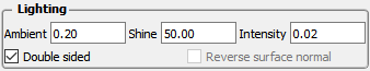
Ambient: ambient shading – the amount of ambient light that a surface reflects. 0 is none and 1 is full.
Shine: Degree of shininess – 0 is dull and 100 is very shiny.
Intensity: Degree of highlight intensity – 0 is none and 1 is full.
Set part Fast display representation (according to Global Viewing Detail Mode):
Box: part is represented as bounding box.
Elements: part is represented according to Element Representation.
Points: part is represented as a point cloud.
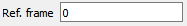
Set part reference frame (Create and Manipulate Frames).
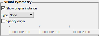
Set part graphical symmetry (Set Symmetry).
Set shading type:
Flat: color and shading are constant across elements
Gouraud: color and shading vary linearly across elements
Smooth: color and shading calculated based on surface normal interpolated across elements to simulate a smooth surface.
Smooth High Quality: Smoothing that attempts to retain subtle features.
See Also
Node, element, and line control how a part's nodes and elements are displayed. Nodes can be displayed as dots, crosses, or spheres. If displayed as crosses or spheres, the radius can be set by the value of a variable at that node. To set using the Node, Element, and Line section:
Right click on the part name in the Parts list and choose or right click on the part in the graphics window and choose , or double click the part in the Parts list.
OR Select → .
By default, any changes you make to will take effect immediately. If you wish to “batch” a series of changes turn on the toggle at the bottom of the dialog. When you are ready to apply a set of changes click the button.
Toggle the Toggle in the top right corner of the dialog.
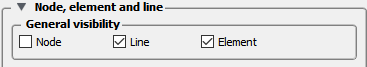
Open the Node, element, and line turndown, then set the desired attribute(s):
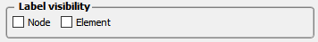
Set visibility of nodes, lines, elements.
Set node/element label visibility (Display Labels).
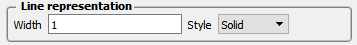
Set Line width and Style (Solid, Dotted, or Dot-dashed)
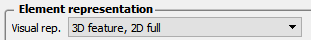
Set Element representation, described below (Change the Visual Representation).
Set element Shrink factor (shrink elements toward the centroid).

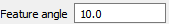
Set angle for Feature Angle representation.
Set Node representation
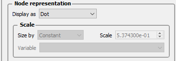
Dot: nodes are displayed as points.
Cross: nodes are displayed as crosses and can be fixed size (size set by the Scale value) or sized based on a variable (and scaled by the Scale value).
Sphere: nodes are displayed as spheres and can be fixed size (size set by the Scale value) or sized based on a variable (and scaled by the Scale value). Sphere detail controlled by Detail value. To avoid hanging up your graphics card, first set your scale using crosses, then turn on spheres.
: particles in an SPH point part are treated as spheres and a surface is extracted on the fly using a screen space voxel grid rendered into an outer surface. See Screen Space Surface Rendering for SPH Solutions for more details.
User defined: for point parts, a reader can provide a mesh to be drawn for each node. When nodes are drawn this way, an orientation can also be applied.
Set polygon reduction. Same model, but simpler representation. Trade-off of visual fidelity and rendering speed.

EnSight provides five representation modes (and three combination modes) for parts (see also Change the Visual Representation):
|
Full |
Every face and edge of every element is displayed. |
|
Border |
Only unshared faces (for 3D parts) or unshared edges (for 2D parts) are displayed. |
|
3D Border, 2D Full |
Display 3D parts in Border representation; display 2D parts in Full representation. This is the default representation for all parts. |
|
3D Feature, 2D Full |
Display 3D parts in Feature representation; display 2D parts in Full representation. |
|
3D nonvisual, 2D Full |
Display 3D parts in Non Visual representation; display 2D parts in Full representation. |
|
Feature Angle |
Only those edges joining faces in the Border representation for which the angle between the faces is less than some threshold are displayed. Feature Angle typically extracts the topological features of interest in a model. |
|
Non Visual |
No visual representation exists on the client. It is often useful to use Non Visual as the representation for 3D computational domain parts - provided you also have some sort of shell part to display the outer surface. |
|
Bounding Box |
Displays a bounding box surrounding (and in place of) the nodes and elements. |
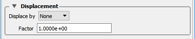
In structural mechanics simulations, a common output variable is a set of vectors representing the movement or displacement of geometry. Each displacement vector specifies a translation of a node from its original position (an offset). EnSight can display and animate these displacements to help visualize the relative motion of geometry. To set Displacement (see also Display Displacements):
Toggle the Advanced Toggle in the top right corner of the dialog.
Open the Displacement turndown.
Set Displace by to either None (no displacement) or the vector variable to use for displacement.
Set nodal displacement factor to reduce or exaggerate a displacement.
Model Parts and clips (because they can be structured parts) will have these available. These will only be applicable to structured parts.
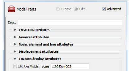
Toggle the Advanced Toggle in the top right corner of the dialog.
Open the IJK axis display turndown.
Toggle IJK Axis Visible to display an IJK axis for the part.
The scale factor for the IJK Axis triad can be modified in this field.