


The following topics are included in this section:
Visual symmetry is an attribute of parts. You can enable display of a mirrored copy of a part into one or more of the seven octants of the part's reference frame. You can also enable display of a number of rotational instances about the x, y, or z axes of the part's reference frame. You can specify an origin for the symmetry. To display visual symmetry:
Select the desired part(s) in the main Parts list.
Click the Visual Symmetry icon from the Part Quick Action Icon Bar.

Visual Mirror Symmetry
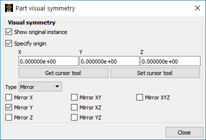
Specify the origin, if necessary.
Select Mirror from the Type pulldown menu.
Select the desired octant(s) from the menu.
Visual Rotational Symmetry
.png)
Specify the origin, if necessary.
Select Rotational from the Type pulldown menu.
Set the number of instances to display.
Note: For rotational periodicity only, the additional section entitled Periodicity - Rotational will be shown. Some additional per part information is required if you are using periodic traces. Here you will specify the rotational periodic axis and the number of sections (instances) which will make 360 degrees. Follow the link to the traces How To that is specified above (or in the See Also section below).
Recall that symmetry is performed with respect to the reference frame of the part. The frame's origin and axes define the partitioning of space into the octants that attached parts are mirrored into, or the rotational axis. If the symmetry operation did not produce the desired effect, it is probably due to the fact that the part's frame is not located/aligned on/with the plane of symmetry, or the rotational symmetry axis, as designed for the model. The solution is to create a new frame, assign the part(s) to the new frame, and position the frame such that two of its axes lie in the plane of symmetry, or one of its axes align with the rotational axis. There operations are discussed in Create and Manipulate Frames.
Visual Symmetry Specify Origin
If the Specify Origin toggle is off, then the origin of your rotation axes is the part reference frame origin. However, If you toggle on the Specify Origin, then this is the origin that will be used (instead of the reference frame origin), and the reference frame of the part will only be used for the direction of the axes.
Note: The origin is specified here in global coordinates. Specifying the origin in this manner is useful if your axes are aligned properly with your model, but you just need the origin to be moved and don't want to go to the trouble of creating, moving and then assigning a new frame to your part(s).
Computational symmetry can be used for unstructured and structured model parts with periodic boundary conditions.
Note: It does not work for created parts.
Computational symmetry can handle rotational, translational, and mirror symmetry. Unlike visual symmetry, computational symmetry actually produces the symmetric geometry and variables on the server - allowing for more than just visual symmetry.
You enable computational symmetry by selecting the frame, specifying the type (Mirror, Translational, Rotational), and setting type specific (such as the rotation angle and the number of instances to create). Each part assigned to the frame will be updated on the server to reflect the specified symmetry.
Note: Each new instance of a part created through computational symmetry creates a new part on the server.
To use computational symmetry, you will need to enable the Frame feature if it isn't already enabled. Then:
→ →
OR
Click the Frame feature from the Feature Icon Bar. If you do not see this option you will need to turn it on by right clicking in the Feature Icon Bar to the ribbon to show the Frame feature.

If the default frame (frame 0) is not correctly positioned for the desired symmetry operation, create a new frame, position the frame in the proper location and orientation, and assign the part(s) to the new frame. See Create and Manipulate Frames.
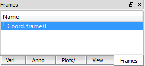
Click the Frame tab then select the desired frame to edit.
Click the Computational Symmetry icon. The remaining steps depend on the type of symmetry desired.
See Create and Manipulate Frames.
Mirror Symmetry is similar to graphical symmetry as described above.
Set the Type to Mirror and set the desired octant(s).
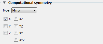
Click .
Rotational Symmetry creates instances by rotating, around the selected axis of the frame, the specified number of degrees. The selected frame’s axis must be aligned with the desired symmetry axis.
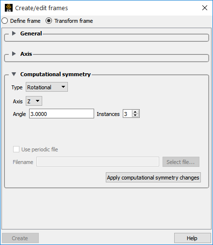
Select Rotational from the Type pulldown.
Select the frame rotational axis.
Set the desired rotation angle (in degrees) in the Angle field.
Set the desired number of instances in the Instances field (number 1 is the original, set Instances to 2 to yield one copy).
If a periodic match file is available, toggle Use Periodic File and enter the file name. Periodic match files are discussed below.
Note: This toggle will be grayed out and unavailable for Case and Case Gold formats because the periodic match file name is entered into the Case file.
Click .
Translational Symmetry creates instances in the direction of the specified translation vector (using the frame to get the x, y, z directions).
Select Translational from the Type pulldown.
Enter the desired translation vector in the XYZ fields and press Return.
Set the desired number of instances in the Instances field (number 1 is the original, set Instances to 2 to yield one copy).
If a periodic match file is available, toggle and enter the file name. Periodic match files are discussed below.
Click .
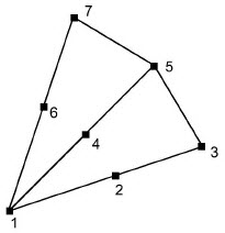
When a model is created with periodic boundary conditions, there is typically a built-in correspondence or match between certain nodes and elements. For example:
The elements defined by nodes 1,2,3 and nodes 1,6,7 should match when rotated about an axis passing through node 1 (perpendicular to the screen). When another instance is created, node 2 matches with 6 and node 3 matches with 7.
When instances are added to a part, it is desirable to eliminate these duplicate nodes. Without a match file, EnSight will attempt to find and remove them using a hashing scheme. This method works quite well, but may not find all duplicates. (Remaining duplicates are usually noticed when the part is in feature angle representation since EnSight treats elements with duplicate nodes as separate - even if they are coincident.)
Note: If you have a periodic match file you do not need to specify the rotation axis and angle in the Frame Computational Symmetry dialog - the value is provided in the file.
A user-supplied matching file can be used to quickly find and remove all duplicates. The match file is a simple ASCII text file. The file for the example above would be (the text in italics is not part of the file):
| rotate_z | specifies rotational symmetry and the applicable axis |
| 52.34 | the angle of rotation (in degrees) |
| 3 | the number of node pairs to follow |
| 1 1 | first node pair |
| 2 6 | second node pair... |
| 3 7 | Periodic Matchfile Format |
See for more information on periodic match files.