


Internal and External Flow
- A simulation that represents internal flow.
- A simulation that represents external flow.
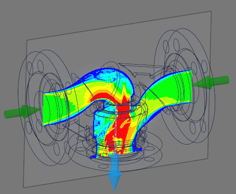
For internal flow simulations, the motion of the fluid material is constrained by physics conditions to the region by walls representing the bounding solid bodies, and may enter or exit the region through inlets, outlets, and openings that represent conditions outside of the modeled region. Examples of internal flow are fluid flowing through compressors, pumps, fans, and pipes.
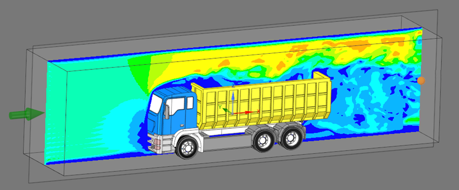
In external flow simulations, the fluid material surrounds the body. Examples of external flow are air flow around an airfoil, vehicle, or any object. When simulating external flow around an object, your geometry might not contain a fully defined external flow boundary. You will create an external flow boundary by defining a bounding box that surrounds the relevant aspects of your geometry, such as around a vehicle.
- Internal Flow: After the internal flow region is defined by the inlets, outlets, and (if relevant) flow caps, the flow volume is extracted automatically. Values for the flow inlet and outlet conditions are shown in the physics tree.
- External Flow: The enclosure volume is automatically created and values for the flow inlet and outlet conditions can be found in the physics tree. Friction will be included on the ground and model surfaces. No friction will be included for the remaining enclosure surfaces.
This section contains the following topics: