


The Spark Ignition (SI) Engine Zonal model is a multi-zone and zero-dimensional model that can be applied to simulate the evolution of gas composition inside the cylinder between intake valve closing (IVC) and exhaust valve opening (EVO) when the engine cylinder is a closed system.
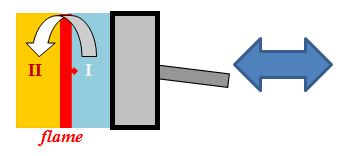
The SI Engine Zonal Simulator consists of two homogeneous "balloon" zones/reactors. The unburned zone/reactor has no inlet and initially contains a fresh fuel-air gas mixture, which will be extracted from the zone after combustion occurs. The burned zone/reactor is initially empty and will be filled with combustion products after ignition. The burned zone allows gas to enter but no gas can leave the zone. In addition, there is a turbulent premixed flame separating the unburned and the burned zones after ignition. The SI Engine Zonal Simulator model treats the flame as an interface with negligible physical size. The purpose of the flame sheet is solely to transform the fresh fuel-air mixture into combustion products.
The SI Engine Zonal Simulation between IVC and EVO can be divided into three distinct stages depending on the presence of mass exchange and zonal mass. The first stage is the pre-combustion stage, which begins at IVC and extends to the start of combustion,  . During the pre-combustion stage, only the unburned zone contains gas and there is no mass exchange. The SI Engine Zonal Simulator model in this stage behaves like a single-zone IC HCCI Engine model.

The second stage is the combustion stage. The combustion process is initiated by energy and ions released from the spark plug at the start of combustion time. The burned kernel expands as the turbulent premixed flame propagates towards the unburned fuel-air mixture inside the cylinder. The mass fraction of the burned gas at a given crank angle can be obtained from the Wiebe function from which the mass flow rate between the zones can be derived. The length of the combustion stage is specified by the burn duration,  , which is a parameter required by the Wiebe function. The SI Engine Zonal Simulator model becomes a true multiple-zone model at this stage because all zones have non-zero mass. Another reason to "isolate" the combustion stage is that the Wiebe function is only valid between
  and
and  +
+  .
.
The flame sheet exists only during the combustion stage ( Figure 8.12: SI Engine Zonal Simulator: Combustion stage ). By assuming complete and instantaneous combustion, the flame should have zero thickness and be adiabatic. The burned gas composition can then be determined by finding the constant-enthalpy, constant-pressure equilibrium state with respect to the gas mixture currently in the unburned zone.
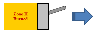
The post-combustion (expansion) stage is the last stage ( Figure 8.13: SI Engine Zonal Simulator: Post-combustion (expansion) stage ). It spans from the end of combustion to EVO. Since no unburned gas is left after the combustion stage (unless the combustion efficiency is less than 1), the unburned zone has no mass and the SI Engine Zonal Simulator model is again reduced to a single-zone IC HCCI Engine model.
The mass exchange rate between the unburned zone and the burned zone is determined by the Wiebe function, which is commonly used to describe the accumulated burned mass fraction in an SI Engine Zonal Simulator. With a given combustion duration and ignition timing, the Wiebe function is expressed as:
 | (8–97) |
where  and
and  are burn duration and the start of combustion (crank angle), respectively.
  is the combustion efficiency and is defined as the mass fraction of gas in the cylinder burned. The Wiebe function itself contains two adjustable parameters,
  and
and  , that could be determined by fitting the experimental burned mass curves of a specific engine. By default, b = 5 and n = 2 are used in the SI Engine Zonal Simulator model. The mass flow rate between burned and unburned zones is the time derivative of Equation 8–98 :
 | (8–98) |
or
 | (8–99) |
Figure 8.14: Burned mass fraction  represented by the Wiebe function
  against crank angle. The effects of the Wiebe function parameters,
  and
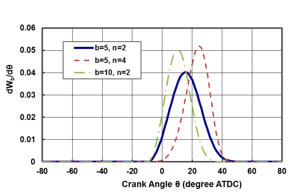
and  , on the burned mass fraction profile are also shown and Figure 8.15: Fuel Consumption rate per crank angle (dW b /d) against crank angle. The effects of the Wiebe function parameters, b and n , on the fuel consumption rate profile are also shown. show typical burned mass fraction and fuel consumption rate profiles given by the Wiebe function and its derivative (with respect to Θ ) against crank angle, respectively.
The gas mixture entering the burned zone through the flame will be at the adiabatic flame temperature with the equilibrium composition corresponding to the instantaneous gas mixture in the unburned zone (with all NOx species fractions set to zero). The adiabatic flame temperature increases during compression because of the energy gain from the piston work.
Figure 8.14: Burned mass fraction represented by the Wiebe function against crank angle. The effects of the Wiebe function parameters, and , on the burned mass fraction profile are also shown
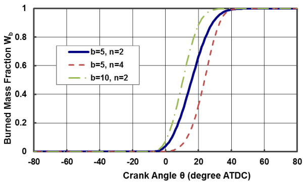
Figure 8.15: Fuel Consumption rate per crank angle (dW b /d) against crank angle. The effects of the Wiebe function parameters, b and n , on the fuel consumption rate profile are also shown.
For the pre- and the post- combustion stages, there is no mass exchange between the unburned and the burned zones. Thus, the zones during these two non-combustion stages can be considered as individual closed homogeneous reactors and the governing equations for the IC HCCI Engine model (or the Multi-Zone HCCI Engine model) can be applied to the SI Engine Zonal Simulator model.
Although the gas mass inside the engine cylinder is constant during the combustion stage, the gas mixture is allowed to come out of the unburned zone and enter the burned zone. Therefore, the governing equations must be modified to include the effect of mass exchange on the gas properties in the zones. Moreover, there are some constraints that must be met during the multi-zone combustion stage:
Pressure is uniform among the zones.
Zone volumes must sum to the cylinder volume.
The outgoing mass flow rate from the unburned zone must equal to the mass flow rate incoming to the burned zone so that the overall mass inside the engine cylinder can be conserved. The mass conservation equation is the same for both zones; the differences occur for the mass flow rates in and out of the zones:
 | (8–100) |
The inlet and the outlet mass flow rates of each zone are given in Table 8.1: Inlet and outlet mass flow rates for the unburned and the burned zones during the combustion stage where  is the mass exchange rate given by Equation 8–99 .
Table 8.1: Inlet and outlet mass flow rates for the unburned and the burned zones during the combustion stage
|
|
| Combustion |
|---|---|---|
|
| | |
| Unburned Zone (zone I) | 0 | |
| Burned Zone (zone II) | | 0 |


The mass exchange has no impact gas composition in the unburned zone because gas is only allowed to leave the zone. On the other hand, species concentrations in the burned zone will be affected by the addition of burned gas products from the premixed flame. Therefore, for the burned zone, the gas species equation will have an additional term to account for the inlet gas effect:
 | (8–101) |
where  and
and  are the molar production rate and molecular weight of species k , respectively. The inlet gas mass fractions
  are given by the equilibrium species mass fractions from the flame. The equilibrium calculation uses the unburned gas properties and assumes both pressure and enthalpy are constant. If there are NO x species in the mechanism, the concentrations of these species are fixed at 0 during the equilibrium calculation.
The gas temperature of the burned zone will be affected by the mass addition. The energy equation for the burned zone will have to include the contribution of the incoming gas:
 | (8–102) |
where  is the enthalpy of the k -th species evaluated at the adiabatic flame temperature, which is determined by the equilibrium calculation.
The governing equation for zone volume is different for each zone. For the unburned zone, the equation of state is used to compute the zone volume:
 | (8–103) |
where  denotes the mean molar weight of gas mixture in the unburned zone.
For the burned zone, the constraint that the zone volumes must sum to the cylinder volume is applied:
 | (8–104) |
where  and
and  are the cylinder volume and its time derivative, respectively.

