


To allow simulation of transient heat effects due to thermal inertia of a reactor wall, or other solid material associated with the reactor, the user now has the option to specify a total heat capacity associated with each reactor module. For transient systems, this heat-capacity effect or thermal inertial will be included in the energy balance of the system. In addition, the possibility for heat exchange between the gas and the wall mass, and between the wall mass and the environment is also optionally included. These extensions allow modeling of the system effects of transient chemical processes or of specifying realistic heating or cooling environments. Such analysis can be critical for determining start-up and cool-down behavior and the effects of varying loads on a reactor system.
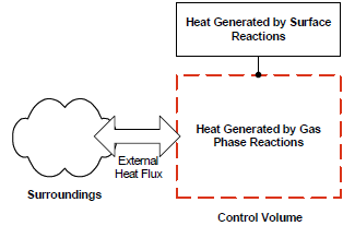
The energy equation, Equation 8–34 , is derived by conserving the thermal energy of an imaginary control volume without considering the presence of a reactor wall. The control volume consists of the gas mixture inside the reactor and the interface between the gas and the reactor wall so that heats of reaction from both gas-phase and surface chemistries are included. A schematic of this control volume is given in Figure 8.4: Schematic of the gas phase control volume in the absence of the reactor wall . Because of the absence of a reactor wall, all heat fluxes interact directly with the gas mixture in the form of the  and
and  terms in the gas-energy balance.
However, when the reactor wall is included in the energy balance, an additional equation is needed to solve for the wall temperature since the wall temperature can be different from the temperature of the gas mixture. To this end, we consider a new reactor-wall control volume, so that the wall energy equation can be established. Furthermore, the original gas-phase control volume is modified to make the gas-wall interface part of the reactor-wall control volume. The new configuration of the control volumes and their thermal energy interactions are shown in Figure 8.5: Schematic of the gas-phase and wall control volumes for energy balance .
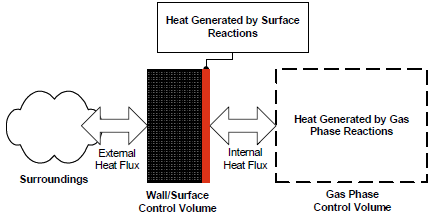
Accordingly, the wall energy-balance equation for Reactor M is given in Equation 8–38 .
 | (8–38) |
As a consequence of including the wall-energy balance, the energy-conservation equation for the gas mixture inside the reactor becomes
 | (8–39) |
In the above equations, the general term for heat-transfer to the external environment has been replaced by a term accounting for heat-transfer between the gas in the reactor and the wall material, where the wall material now interacts exclusively with the external environment. Since convection is the dominant heat-transfer mechanism between the gas mixture and the reactor wall, the heat flux can be cast into the following form:
 | (8–40) |
To enable Equation 8–39 and Equation 8–40 , the user must supply the gas-to-wall convective heat-transfer coefficient as well as the thermal mass and heat capacity of the reactor wall. These input parameters are provided through the Ansys Chemkin Interface.