Conservation of mass, energy, and species for a well mixed reactor or homogeneous system include net generation of chemical species within the reactor volume, and net loss of species and mass to surfaces in the reactor. Homogeneous systems include closed batch reactors, single-zone engine-cylinder models, perfectly stirred reactor approximations, and well mixed (low-pressure) plasma processing reactors, for example.
In closed batch reactors, there are no inlets or outlets flow during the period of interest, although there may or may not be heat flow to the external environment. Such batch systems are inherently transient, where the chemical state changes as production and destruction of species progress through chemical reaction. A perfectly stirred reactor (PSR) consists of a chamber, which may or may not allow heat loss, having inlet and outlet ducts. There may be more than one inlet defined for each reactor.
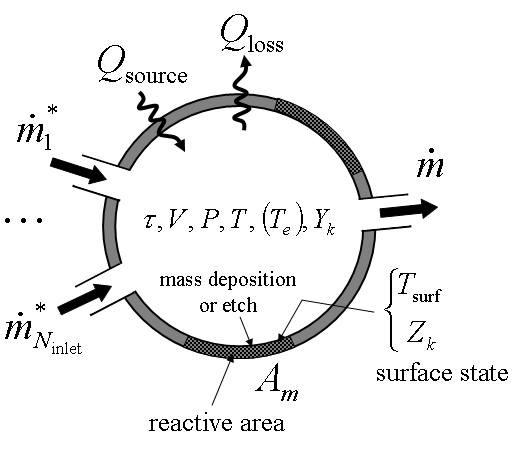
Figure 8.1: Schematic Representation of a Well Mixed Reactor Module illustrates the conceptual representation of a generic reactor chamber. A steady flow of reactants is introduced through the inlet with a given species composition and temperature. For transient systems, there may be no flow, such that the system is closed with respect to mass transfer other than surface losses or gains. In some cases, the sum of the mass flow rates into the reactor, , may not be equal to the mass flow rate out of the reactor,
, due to deposition on or etching of surface materials. For open systems, the reactor pressure is specified, so that the conservation equations determine the volume outflow. Although Figure 8.1: Schematic Representation of a Well Mixed Reactor Module depicts a single surface in the reactor, an actual reactor may contain many different material surfaces, such as reactor walls, silicon wafer, substrate holder, etc. Each of these materials may have a different set of reaction kinetics associated with it. For this reason, we have included the capability of defining multiple surface materials that represent different fractions of the total surface area, with corresponding surface chemistry mechanisms.
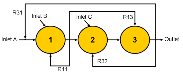
In addition to modeling a single well mixed reactor, Ansys Chemkin allows the user to build a reactor "cluster" composed of many reactor modules connected in series, with the possibility of "recycling" streams feeding back to upstream reactors or being directed forward to downstream reactors. A schematic of such a reactor cluster is given in Figure 8.2: Schematic Representation of a Reactor Cluster . This cluster is included for illustrative purposes only, to show the options for connecting reactors. The symbols R11 , R13, and R32 are examples of recycling streams, defined as fractions of total mass flow out of a reactor.
Reactor clusters are created using the Graphical User Interface Diagramming tool, as
described in Chemkin Getting Started Guide
. This allows you to drag and drop reactors and connect them using mass-flow streams. Each inlet
stream can be assigned it’s own attributes for flow rates, gas temperature, and
composition. Recycling streams can be defined by specifying the fraction of the outflow from one
reactor that will flow into another reactor. By default the outflow of a reactor will flow 100
percent into the next (downstream) reactor in series. When recycling streams are defined by the
user, the mass flow from one PSR to the next in series will be one minus the sum of the recycle
flows defined from that reactor to all other reactors (for example, in Figure 8.2: Schematic Representation of a Reactor Cluster
, R12 = 1 - R11 -
R13 ).
As an example, the following set of keywords could be entered to define the reactor network shown in Figure 8.2: Schematic Representation of a Reactor Cluster :
INLET inletA 1  ! this indicates inletA is associated with reactor (PSR) 1
INLET inletB 1
INLET inletC 2
RECY  1  1  0.10  ! recycle 10% of PSR 1 outflow back into PSR 1
RECY  1  3  0.30  ! 30% of PSR 1 outflow into PSR 3
RECY  3  2  0.25  ! 25% of PSR 3 outflow recycled to PSR 2 ...


