


In this section, to further demonstrate Ansys Chemkin’s capabilities, we will take the thermal-cycle reactor network created in the previous sections and add to it a reactor that will perform selective catalytic reduction (SCR). Note that in Pre-Processing, we already included the surface chemistry necessary to enable the SCR reactions in our Chemistry Set.
Open the Diagram View panel by double-clicking the Thermal_Cycle Diagram View in the project tree.
Click the Outlet icon to select it, then right-click and select Delete Item from the context menu. The icon will be deleted, which will allow you to add another reactor.
On the Diagram, click the last PSR in the series. This will highlight the icon in cyan.
Click the PFR (plug-flow reactor) icon on the Models Palette. The icon should appear on the Diagram with a connection drawn between the PSR that you had highlighted in the previous step.
Keeping the PFR icon selected, click the Outlet icon from the Models Palette. The Outlet icon should appear on the Diagram with a connection drawn from the PFR.
Use the Update button to verify the connection. Note that the PFR will not be solved simultaneously with the other thermal-cycle components, but will instead be solved after the PSR system has been computed, since the groups of PSRs compose a separate Cluster from the PFR (another Cluster within itself). The inter- and intra-cluster connections can be represented by different types of lines, the styles of which can be selected by clicking on the Display Options button at the bottom of the Diagram window.
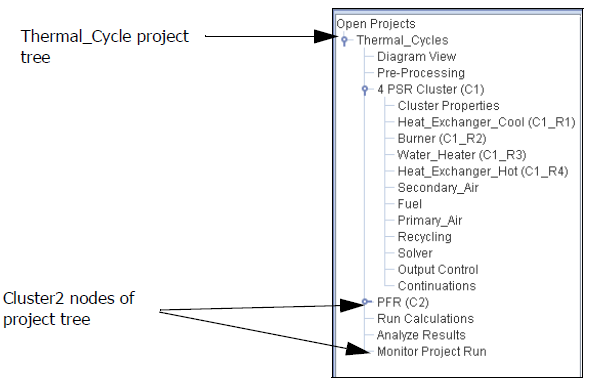
Rename the C2_PFR reactor, either on the Project Tree or on the Diagram View, to Catalytic_Converter. Click the Update Project button to update both the Diagram and the Open Projects tree.
To set the properties of the converter, double-click the Catalytic_Converter (C2) node on the Open Projects tree. In the Reactor Physical Properties tab, select Solve Gas Energy Equation for the problem type and set the length of the converter channel (Ending Axial Position) to be 25 cm. Also set the Cross-sectional Area to be 2000.0 cm2 and the Internal Surface Area per Unit Length to be 5000.0 cm (Figure 2.51: Catalytic_Converter (C2_R1)-Reactor Physical Properties).
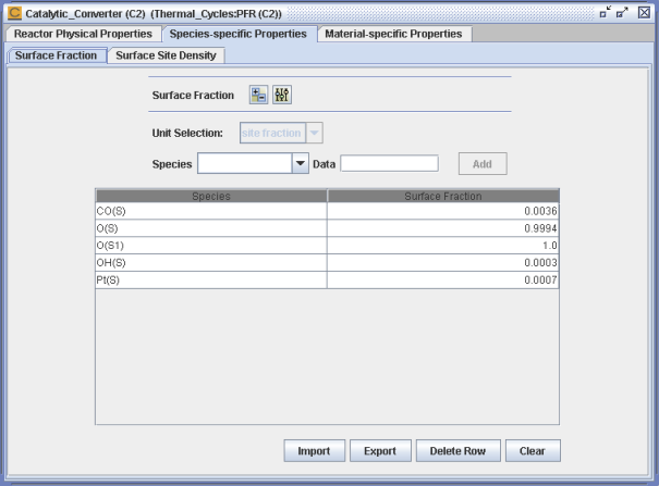
Select the Species-specific Properties tab and set the initial surface species site fractions as shown in Figure 2.52: Catalytic_Converter (C2_R1)-Species-specific Properties-Surface Site Fractions. This step is necessary to provide an initial guess of the surface state at the inlet to the converter when the gas first enters.
Select the Material-specific Properties tab and set the Surface Area Fraction for the two available materials, so INERT=0.0 and 2WAYCATALYS=1.0. For this PFR reactor, we want all of the internal surface area to have the catalytic-converter chemistry active, and none to be considered "inert".
Double-click the Output Control node for Cluster2 on the Open Projects tree, and set the distance interval for printing to 1.0 cm. This will result in 25 states being written to the diagnostic output file for this reactor.
Save the modified project (Ctrl-S).
Note: Note that it is not necessary to specify inlet parameters for the Catalytic_Converter (PFR) reactor, because they are determined entirely by the upstream Cluster.
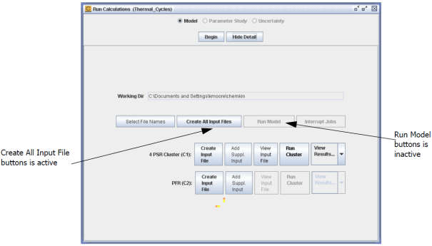
Open the Run Calculations panel from the project tree. As shown in Figure 2.53: Clustered Run Calculations > Create Input File Buttons, the panel is usually compact, but you can click the Display Details button to display file-creation and run buttons for both clusters in the project. To create input files for both clusters, click on the Create All Input Files button.
Click the Run Model button. As each cluster is solved, the associated View Results and Post-Processor buttons will become active.

Note: Simulation for a multiple-cluster project is achieved by running each cluster in succession. The Cluster1 solution file is used to initialize the run for Cluster2. With the Run Model button, Ansys Chemkin will automatically run all the clusters in succession. Using the Run Cluster button will launch the simulation for that specific cluster. For a downstream cluster (for example, Cluster2), using the Run Cluster button causes the user to be prompted for the Cluster1 solution file.