


A Surface of Revolution is a surface created by revolving a polyline about an axis. The polyline may be as simple as a single line segment or as complicated as a general curve.
The following characteristics of surfaces of revolution will be discussed:
Note: There are several ways to insert a surface of revolution:
From the menu bar, select Insert > Location > Surface of Revolution.
From the toolbar, select Location > Surface of Revolution.
Depending on the context, you may be able to perform an insert from the shortcut menu in the tree view.
For details, see Domains.
The Method setting has the following options:
| Option | Description |
|---|---|
|
| Creates a cylinder using two axial and one radial coordinate points. |
|
| Creates a cone using two axial and radial coordinate points. |
|
| Creates a disc using one axial and two radial coordinate points. |
|
| Creates a cylinder using one axial and radial coordinate points. |
|
| Enables you to specify a line or polyline to revolve about the axis (to be specified later). |
These fields are not available for the From Line option. These fields specify axial and radial coordinates to define
the surface of revolution.
Only one set of coordinates are available for the Sphere option. The axial value offsets the sphere in the
direction of the rotational axis, and the radial value is used as
the radius of the sphere.
Line is available only if the From Line option is selected. The Line setting selects a valid line or polyline to use for rotation around
the axis.
Tip: Click the Location Editor  icon to open the Location Selector dialog box, which displays the complete list of available lines.
Note: Calculations of quantities (such as area) performed on
a surface of revolution created using the From Line option may be incorrect in the following situations:
Multiple input lines are selected with overlapping segments.
An input line passes through a region where multiple domains overlap. Domains may overlap in a single case or between multiple cases if more than one case is loaded.
To ensure that calculations are correct, these situations should be avoided.
# of Samples is not available if the From Line option is selected. The # of Samples setting sets the amount of sample points in the direction of the
rotational axis.
The Theta Samples setting specifies the amount of sample points evenly rotated around the rotational axis. For example, increasing this setting would make a cylinder's curve around its origin more accurate (more like a circle).
The Method setting has the following options:
| Option | Description |
|---|---|
|
| Enables you to specify a principal axis to rotate around. |
|
| Enables you to specify a custom axis to rotate around using a line. |
Axis is available only if the Principal Axis option is selected. The Axis setting enables you to select from a list the X, Y, or Z axis to
rotate around.
Select the Angle Range check box if you want to specify a minimum or maximum angle to rotate to.
These settings specify a start and end offset for the radius.
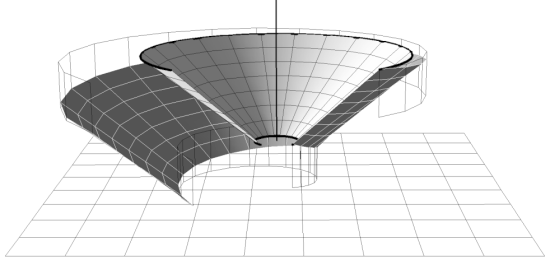
The following image shows two partial cones with the same profile and theta limits. For the end profile of one of the cones, the radial offset is positive and the axial offset is negative, causing the radius to increase and the axial coordinate to decrease with increasing theta (as determined by the right hand rule with reference to the axis shown). Two other surfaces of revolution were included in the figure to help illustrate axial displacements.
The color settings can be changed by clicking the Color tab. For details, see Color Tab.
The rendering settings can be changed by clicking the Render tab. For details, see Render Tab.
The View tab is used for creating or applying predefined Instance Transforms for a wide variety of objects.
For details on changing the view settings, see View Tab.