Benchmark D2
VMD2
Barrel Vault Roof Under Self Weight
Overview
Test Case
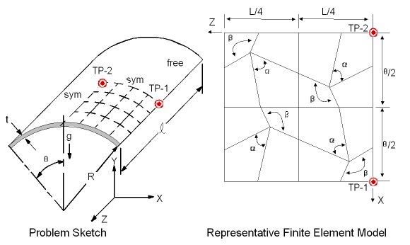
A cylindrical shell roof is subjected to gravity loading. The roof is supported by walls at each end and is free along the sides. Monitor the y-displacement and bottom axial stress (σz) at target point 1 along with the bottom circumference stress (σθ) at target point 2 for a series of test cases with varying skew angle β for each element type. A companion problem that studies uniform element mesh refinement is VMC3.
| Material Properties | Geometric Properties | Loading and Boundary Conditions | |||||||||||||
|---|---|---|---|---|---|---|---|---|---|---|---|---|---|---|---|
|
|
|
Target Solution
Target solution is obtained using a uniform 8 x 8 quadrilateral mesh of an 8-node quadrilateral shell element, (see R. D. Cook, Concepts and Applications of Finite Element Analysis).
| ETYP | Beta (Deg.) | Alpha (Deg.) | UY (1), in | Axial Stress (1) Bottom,kPa | Hoop Stress (2) Bottom,kPa |
|---|---|---|---|---|---|
| -- | 90 | 90 | -.3016 | 358.42 | -213.40 |
Results Comparison - Quadrilateral Elements
| Ratio | |||||
|---|---|---|---|---|---|
| ETYP | Beta | Alpha | UY (1) | Axial Stress (1) Bottom | Hoop Stress (2) Bottom |
| 181 | 65 | 133.4 | 1.019 | 0.946 | 0.918 |
| 181 | 77.5 | 106 | 1.037 | 0.950 | 0.965 |
| 181 | 90 | 90 | 1.048 | 0.940 | 0.983 |
| 181 | 110 | 75.1 | 1.056 | 0.910 | 0.956 |
| 181 | 130 | 66.2 | 1.055 | 0.863 | 0.889 |
| 281 | 65 | 133.4 | 0.974 | 0.985 | 1.133 |
| 281 | 77.5 | 106 | 0.999 | 0.967 | 1.049 |
| 281 | 90 | 90 | 1.004 | 0.953 | 1.027 |
| 281 | 110 | 75.1 | 0.994 | 0.949 | 1.049 |
| 281 | 130 | 66.2 | 0.971 | 0.960 | 1.059 |
Assumptions, Modeling Notes, and Solution Comments
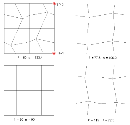
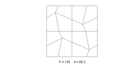
The problem is designed to test singly-curved shell elements under combined membrane and bending deformation. The solid model is set up to produce irregular element shapes for quadrilateral elements. The angle β is prescribed, while the angle α is calculated from the resulting geometry. The range of β is set such that all element interior angles fall within 90° ± 45°.
The target solution is obtained from the author's 8-node shell element, (see R. D. Cook, Concepts and Applications of Finite Element Analysis), under a uniform rectangular element geometry using an 8 x 8 mesh pattern.
Results for uniform quadrilateral element shapes are noted in the tabular and graphical output for β = 90° and should be used as a basis for comparison of distorted element performance.
Displacement results over the range of element distortion vary the greatest for SHELL181. In this problem, SHELL281 predict the displacements more accurately for mild element geometry distortion.
Axial (σz) stress results, over the range of element distortion, show some variation for SHELL181, and SHELL281 elements. Hoop (σθ) stress results are less affected by irregular element shapes except at the extreme β angle range.


