


Benchmark D3
VMD3
Free-Free Vibration of a Solid Beam
Overview
Test Case
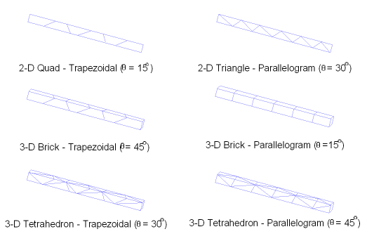
A free-free solid beam is analyzed to determine the first axial and bending mode natural frequencies. The axial and bending modes are extracted using the Block Lanczos eigenvalue extraction method. Examine the influence of rectangular, trapezoidal, and parallelogram element shape models on the eigenvalue calculations.

| Material Properties | Geometric Properties | Loading and Boundary Conditions | |||||||||||
|---|---|---|---|---|---|---|---|---|---|---|---|---|---|
|
|
|
Target Solution and Results Comparison
Target Solution:
Freq = 208.333 Hz (Axial Mode)
Freq = 7.138 Hz (Bending Mode)
Results Comparison:
| 1st Natural Frequency Ratio | ||||||
|---|---|---|---|---|---|---|
| Axial Mode | ||||||
| Shape | Angle | PLANE182 | PLANE183 | SOLID185 | SOLID187 | SOLID186 |
| Rectangular | 0 | 1.003 | 1.000 | 1.003 | 1.000 | 1.000 |
| Trapezoidal | 15 | 1.003 | 1.000 | 1.003 | 1.000 | 1.000 |
| Trapezoidal | 30 | 1.003 | 1.000 | 1.004 | 1.000 | 1.000 |
| Trapezoidal | 45 | 1.004 | 1.000 | 1.005 | 1.000 | 1.000 |
| Parallelogram | 15 | 1.003 | 1.000 | 1.003 | 1.000 | 1.000 |
| Parallelogram | 30 | 1.003 | 1.000 | 1.003 | 1.000 | 1.000 |
| Parallelogram | 45 | 1.003 | 1.000 | 1.003 | 1.000 | 1.000 |
| Bending Mode | ||||||
| Rectangular | 0 | 1.010 | 0.999 | 1.010 | 1.004 | 1.002 |
| Trapezoidal | 15 | 1.567 | 1.000 | 1.598 | 1.005 | 1.003 |
| Trapezoidal | 30 | 1.973 | 1.003 | 2.015 | 1.008 | 1.010 |
| Trapezoidal | 45 | 2.207 | 1.012 | 2.254 | 1.020 | 1.051 |
| Parallelogram | 15 | 1.040 | 0.999 | 1.043 | 1.005 | 1.002 |
| Parallelogram | 30 | 1.091 | 0.999 | 1.097 | 1.009 | 1.004 |
| Parallelogram | 45 | 1.119 | 0.999 | 1.127 | 1.020 | 1.010 |
Assumptions, Modeling Notes, and Solution Comments
The problem tests the influence of irregular element shapes on eigenvalue calculations. Although the problem appears rather simplistic in nature, it is a severe test for linear irregular shaped elements where accurate bending mode frequencies are required.
Since the beam is free of any constraints, only one-half of the beam is required for modeling. Symmetry constraints are applied at the mid-length of the models. To obtain the desired bending mode (in the XY plane) all nodes at Z = 0 are constrained in the Z direction. Additionally, for the axial mode only, all nodes at Y = 0 are constrained in the Y direction.
All load cases show good agreement in the prediction of the first axial natural frequency. This mode is simply linearly-varying longitudinal motion which is easily handled by both linear and quadratic elements. Irregular element shapes have only a minor effect on solution accuracy since axial motion is predominant.
For the linear elements (PLANE182, SOLID185), prediction of the first bending mode is significantly affected by irregularly shaped elements. If the elements are distorted, the stiffness of the element increases hence over predicting the bending mode natural frequency.
For the quadratic elements (PLANE183, SOLID186, SOLID187), prediction of the first bending mode is very good. Irregular element shapes for quadratic elements have little effect on the solution accuracy.