


VM303
VM303
1D Steady-State Thermal Conduction in a Reinforced Block
Overview
| Reference: | Latif M. Jiji. Heat Conduction. 3rd Ed. Springer. 2009: 24-25. |
| Analysis Type(s): | Steady-State Thermal (ANTYPE = 0) |
| Element Type(s): |
3D 8-Node Thermal Solid Elements (SOLID278) 3D 20-Node Thermal Solid Elements (SOLID279) 3D Conduction Bar Elements (LINK33) 3D Reinforcing Elements (REINF264) 3D Coupled-Field Link Elements (LINK228) |
| Input Listing: | vm303.dat |
|
VM303 requires a supplemental .cdb input file which is too long to include full input listings. This file must be downloaded and placed in your working directory for the test case to run properly. Additionally, the geometry and mesh should be regenerated. Download link: MAPDL Test Case Files for 2024 R2 vm303_1.cdb vm303_2.cdb vm303_3.cdb vm303_4.cdb |
Test Case
A thermally non-conducting cubic block of side L is reinforced with a conducting bar of small cross-section area. The bar begins from one face which is at a temperature To and ends at the opposite face which is at a temperature TL:
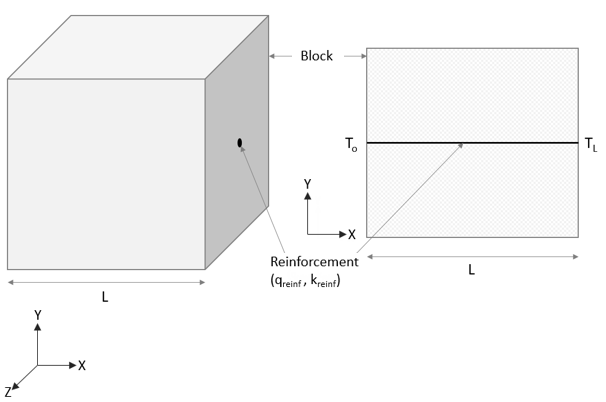
The thermal conductivity (kreinf) and the heat generated (qreinf) by the reinforcing bar are known.
In the first four cases, heat load equivalent to qreinf is applied to the reinforcing/link element. In the fifth and sixth cases, a potential difference is applied to the LINK228 elements which produces the electric current. The values of the potential difference and the resistivity are chosen so that the joule heat produced by the electric current is equal to the heat load (qreinf) in the first four cases.
Determine the maximum temperature (Tmax) on the bar.
| Case # | Material Properties | Geometric Properties | Loading |
|---|---|---|---|
| 1 - 4 |
kreinf = 1 W/mm°C |
L = 10 mm
Cs area of reinforcing/link = 0.0004 mm2 |
To = 20°C TL = 80°C qreinf = 6 W/mm3 |
| 5 & 6 |
kreinf = 1 W/mm°C RSVXreinf = 0.001 Ohm |
L = 10 mm Cs area of link = 0.0004 mm2 |
To = 20 °C TL = 80 °C Vo = 0 VL = 0.7746 |
Analysis Assumptions and Modeling Notes
Six cases are considered. The first case uses the SOLID278 and REINF264 elements. The second case uses the SOLID278 and embedded lower-order LINK33 elements. The third case uses the SOLID279 and REINF264 elements. The fourth case uses the SOLID279 and embedded higher-order LINK33 elements. The fifth case uses the SOLID278 and embedded lower-order LINK228 elements with KO(1)110, thermal-electric. The sixth case uses the SOLID279 and embedded higher-order LINK228 elements with KO(1)110, thermal-electric. The reinforcing elements are created with the EREINF command while the embedded elements connections between base and embedded elements are created with EEMBED command.
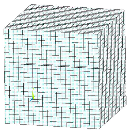
To avoid cases of volume overloading with reinforcements, the cross-section area of the reinforced bar is small compared to the meshed area of the block around its vicinity. The meshes are generated in such a way that the maximum temperature can be accounted for.
Results Comparison
| Steady-State Thermal Analysis | Target | Mechanical APDL | Ratio |
|---|---|---|---|
| SOLID278 + REINF264 | |||
| Maximum Temperature (Tmax) | 128.000 | 128.000 | 1.000 |
| SOLID278 + LINK33 (2-NODED) | |||
| Maximum Temperature (Tmax) | 128.000 | 127.999 | 1.000 |
| SOLID279 + REINF264 | |||
| Maximum Temperature (Tmax) | 128.000 | 128.000 | 1.000 |
| SOLID279 + LINK33 (3-NODED) | |||
| Maximum Temperature (Tmax) | 128.000 | 127.999 | 1.000 |
| SOLID278 + LINK228 (2-NODED) | |||
| Maximum Temperature (Tmax) | 128.000 | 128.001 | 1.000 |
| SOLID279 + LINK228 (3-NODED) | |||
| Maximum Temperature (Tmax) | 128.000 | 128.001 | 1.000 |