VM302
VM302
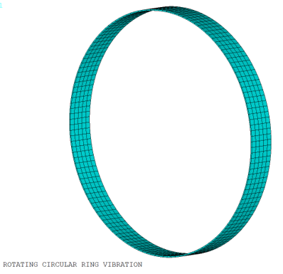
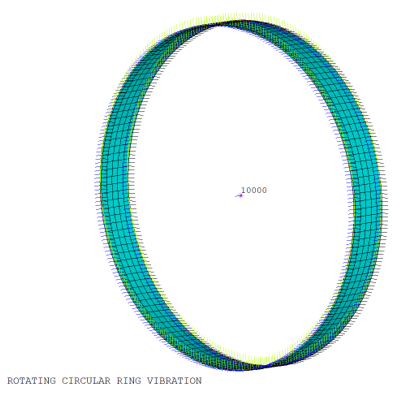
Rotating Circular Ring
Overview
| Reference: | Giancarlo Genta. Dynamics of Rotating Systems. 2005: 535. |
| Analysis Type(s): |
Static Analysis (ANTYPE = 0) Linear Perturbation Modal Analysis (ANTYPE = 2) |
| Element Type(s): |
8-Node Structural Shell (SHELL281) 20-Node Structural Solid (SOLID186) 2D / 3D Node-to-Surface Contact Elements (CONTA175) 3D Target Segment Elements (TARGE170) |
| Input Listing: | vm302.dat |
Test Case
A thin circular ring is examined to determine the influence of the stress-stiffening, spin-softening, and Coriolis effect on in-plane modes, where displacements take place in the plane perpendicular to the rotational axis.
A linear perturbation modal analysis is performed to determine the natural frequencies and mode shapes. Contact elements are used at both edges to prestress the ring and the modal analysis is performed with a free-free boundary condition.
| Material Properties (Steel) | Geometric Properties | Loading | ||
| E = 2.1E11 Pa | Outer diameter = 176 mm | Rotational Velocities:
| ||
| DENS = 7850 kg/m3 | Thickness = 0.88 mm | |||
| Nuxy = 0.3 | Width = 20 mm |
Analysis Assumptions and Modeling Notes
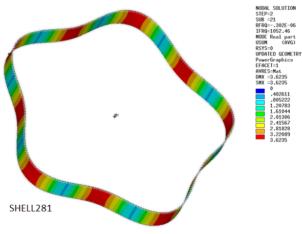
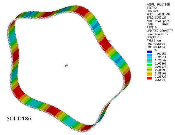
The ring is first modeled with SHELL281 elements with quadratic shape function and midside nodes to enhance element accuracy. Then SOLID186 is used.
A linear perturbation modal analysis is performed. The base nonlinear static analysis enables to prestress the ring using node-to-surface contact element (CONTA175 and TARGE170) and the multipoint forced-distributed constraint option.
The Coriolis effect is enabled (CORIOLIS) in a rotating reference frame to apply spin-softening and the Coriolis forces to the rotating structure.
A static analysis restart with perturbation from the previous analysis is performed. A modal analysis is performed using the damped method. At this point, no constraints are applied to compare the results with analytical formulas established for a free ring.
Natural frequencies of in-plane modes are determined via the Campbell procedure (CAMPBELL) and compared to the analytical solution at rest and at 12000 rpm.
Note: The compared modes are in-plane modes corresponding to nodal diameters 2, 3, 4 and 5.
Results Comparison
| Using SHELL281 | |||
|---|---|---|---|
| Mode | Target | Mechanical APDL | Ratio |
| Rotational speed = 0 (rpm) | |||
| MODE1 | 75.299 | 74.1406 | 0.985 |
| MODE2 | 75.299 | 74.1406 | 0.985 |
| MODE3 | 209.9291 | 209.7815 | 0.999 |
| MODE4 | 209.9291 | 209.7815 | 0.999 |
| MODE5 | 400.1857 | 402.443 | 1.006 |
| MODE6 | 400.1857 | 402.443 | 1.006 |
| MODE7 | 645.3431 | 651.2378 | 1.009 |
| MODE8 | 645.3431 | 651.2378 | 1.009 |
| Rotational speed = 12000 (rpm) | |||
| MODE1 | 91.5352 | 91.1274 | 0.996 |
| MODE2 | 411.5352 | 411.1907 | 0.999 |
| MODE3 | 403.8991 | 403.7187 | 1.000 |
| MODE4 | 643.8991 | 643.8325 | 1.000 |
| MODE5 | 717.3123 | 718.2368 | 1.001 |
| MODE6 | 905.5476 | 906.5904 | 1.001 |
| MODE7 | 1049.3712 | 1052.4598 | 1.003 |
| MODE8 | 1203.2173 | 1206.4112 | 1.003 |
| Using SOLID186 | |||
|---|---|---|---|
| Mode | Target | Mechanical APDL | Ratio |
| Rotational speed = 0 (rpm) | |||
| MODE1 | 75.299 | 74.1408 | 0.985 |
| MODE2 | 75.299 | 74.1408 | 0.985 |
| MODE3 | 209.9291 | 209.782 | 0.999 |
| MODE4 | 209.9291 | 209.782 | 0.999 |
| MODE5 | 400.1857 | 402.4418 | 1.006 |
| MODE6 | 400.1857 | 402.4418 | 1.006 |
| MODE7 | 645.3431 | 651.2299 | 1.009 |
| MODE8 | 645.3431 | 651.2299 | 1.009 |
| Rotational speed = 12000 (rpm) | |||
| MODE1 | 91.5352 | 91.1194 | 0.995 |
| MODE2 | 411.5352 | 411.173 | 0.999 |
| MODE3 | 403.8991 | 403.6767 | 0.999 |
| MODE4 | 643.8991 | 643.7645 | 1.000 |
| MODE5 | 717.3123 | 718.1379 | 1.001 |
| MODE6 | 905.5476 | 906.4491 | 1.001 |
| MODE7 | 1049.3712 | 1052.2708 | 1.003 |
| MODE8 | 1203.2173 | 1206.1638 | 1.002 |