VM301
VM301
Critical Speed of a Rotating Disk
Overview
| Reference: | D.S. Dugdale. "Stiffness of a Spinning Disc Clamped at its Centre." J. Mech. Phys. Solids. 1966: Vol 14. |
| Analysis Type(s): |
Static Analysis (ANTYPE = 0) Linear Perturbation Modal Analysis (ANTYPE = 2) |
| Element Type(s): |
8-Node Structural Shell (SHELL281) 20-Node Structural Solid (SOLID186) |
| Input Listing: | vm301.dat |
Test Case
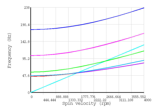
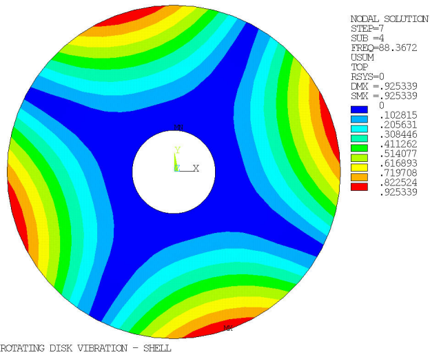
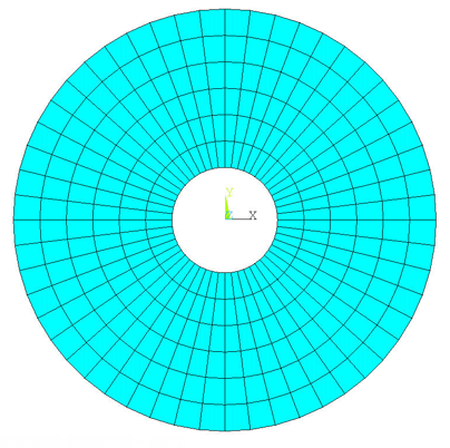
A thin disk with a clamped center hole is modeled. It has a rotational velocity about the axis perpendicular to the disk. Multiple linear perturbation modal analyses are performed at different rotational velocities to generate a Campbell diagram and calculate the critical speed.
| Material Properties (Steel) | Geometric Properties | Loading |
| Young's Modulus = 2.03e+11 N/m2 | Inside Diameter = 6 in. | Maximum Rotational Velocity = 4000 rpm |
| Density = 7850 kg/m2 | Outside Diameter = 24 in. | |
| NU = 0.3 | Thickness = 0.12 in. |
Analysis Assumptions and Modeling Notes
The disk is first modeled using 8-Node shell elements (SHELL281), then 20-Node solid elements (SOLID186).
Because of the geometric properties of the disk, linear prestress is used. A linear perturbation modal analysis follows the static run. The Coriolis effect (CORIOLIS) is not applied in the rotating reference frame because the flexural vibration direction is along the rotational velocity axis (and the Coriolis effect would therefore be zero).
The Campbell diagram is generated (CAMPBELL, then PLCAMP and PRCAMP) for an excitation at twice the rotational velocity, corresponding to the modes with two nodal diameters. The critical speed is then retrieved (*GET).