VM296
VM296
Radial Expansion of a Thermoplastic Cylinder
Overview
Test Case
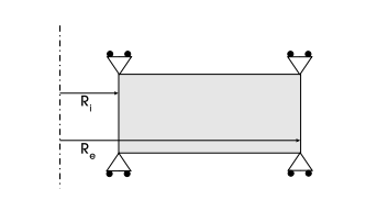
An infinitely long thermoplastic cylinder is modeled with an internal radius of 0.1 m and an external radius of 0.2 m. A bilinear isotropic hardening plastic material with linear thermal softening on initial yield stress is applied to the cylinder model. Nonlinear transient analysis is performed with a ramped radial displacement loading on the inner surface of the cylinder for four different loading durations: 0.001 s, 1.3 s, 13 s, and 130 s. The temperature variation and equivalent plastic strain computed for an infinitely fast process (end time of 0.001 s) is computed and compared against the reference values (Table 2, pg. 5629).
| Material Properties | Geometric Properties | Loading | ||||||||||||||
|---|---|---|---|---|---|---|---|---|---|---|---|---|---|---|---|---|
|
|
|
Analysis Assumptions and Modeling Notes
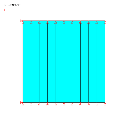
The cylinder is modeled using 2D axisymmetric coupled-field elements PLANE222 and PLANE223 with structural thermal coupling option. The meshing is composed of ten elements in the radial direction and one element in the axial direction. The axial degrees of freedom are constrained to simulate an infinitely long cylinder. The external surface of the cylinder is considered to be adiabatic and the heat is conducted only along the radial direction. The bilinear isotropic hardening plastic material is assigned via TB,PLASTIC,,,BISO with temperature-dependent yield stress and tangent modulus (TBTEMP and TBDATA). The yield stress for different temperatures is calculated using equations 67 and 68 given in the reference material.
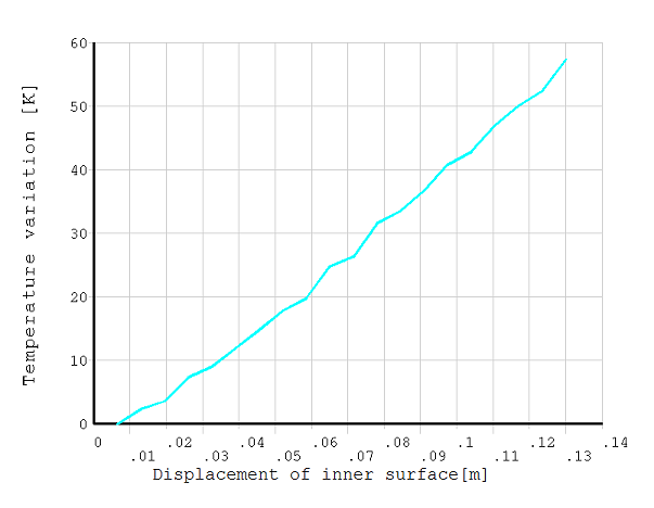
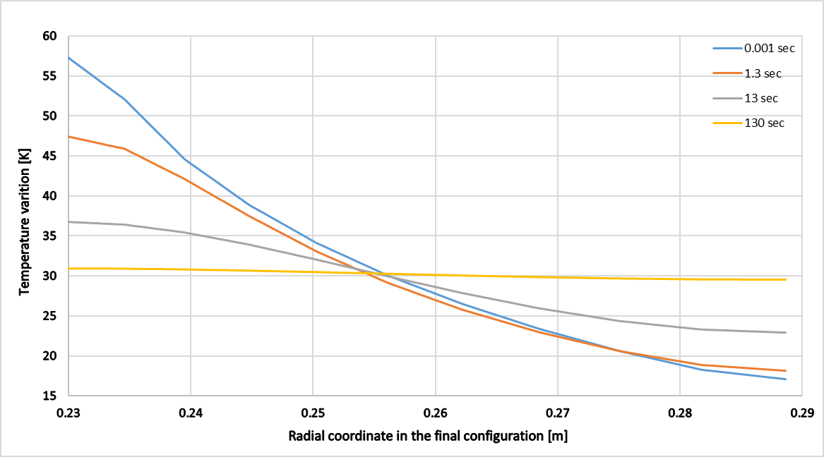
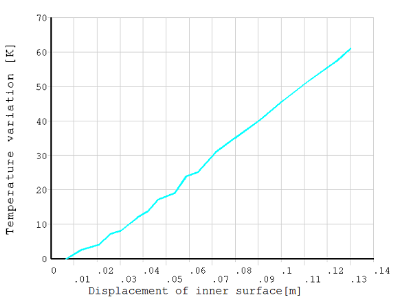
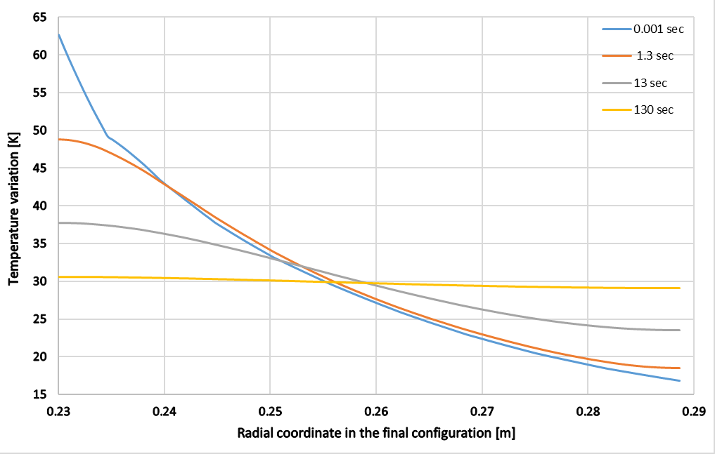
Transient analysis with load duration of time 0.001 s is set to simulate the infinitely fast process (an adiabatic process) when time approaches 0. The calculated minimum and maximum temperature increase and equivalent plastic strain obtained from the infinitely fast process with PLANE222 and PLANE223 elements are compared against the reference values. The temperature variations with respect to displacement on the inner surface for PLANE222 and PLANE223 elements are plotted in Figure 522: Evolution of the Temperature on the Internal Surface (PLANE222) and Figure 524: Evolution of the Temperature on the Internal Surface (PLANE223). The temperature distribution with respect to radial coordinate in the final configuration is also computed for all loading duration using PLANE222 and PLANE223 elements and plotted in Figure 523: Temperature Distribution for Different Loading Duration (PLANE222) and Figure 525: Temperature Distribution for Different Loading Duration (PLANE223).
Results Comparison
| PLANE222 | Target | Mechanical APDL | Ratio | |
| Minimum Temperature Variation (K) | 16.500 | 17.087 | 1.036 | |
| Maximum Temperature Variation (K) | 57.000 | 57.256 | 1.004 | |
| Minimum Equivalent Plastic Strain | 0.426 | 0.430 | 1.009 | |
| Maximum Equivalent Plastic Strain | 0.932 | 0.914 | 0.980 | |
| PLANE223 | Minimum Temperature Variation (K) | 17.400 | 16.822 | 0.967 |
| Maximum Temperature Variation (K) | 58.900 | 62.668 | 1.064 | |
| Minimum Equivalent Plastic Strain | 0.426 | 0.423 | 0.993 | |
| Maximum Equivalent Plastic Strain | 0.935 | 0.937 | 1.002 |