VM288
VM288
Electrical Input Admittance on a Piezoelectric Transducer
Using the Enforced Motion Approach
Overview
Test Case
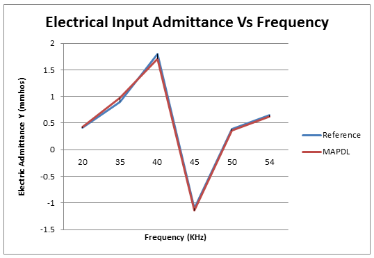
A composite piezoelectric transducer is made of a piezoceramic (NEPEC 6), aluminum, and an adhesive layer. Electrical terminals are attached to electroded surfaces of the piezoceramic where a potential V is applied. Determine the terminal input admittance Y over a frequency range spanning the first natural frequency using mode-superposition harmonic analysis with enforced motion loading.

| Material Properties | Geometric Properties | Loading | |||||||||||||||
|---|---|---|---|---|---|---|---|---|---|---|---|---|---|---|---|---|---|
|
|
|
Constitutive Matrices
NEPEC 6 "Stiffness" Matrix [c] x 10-10 N/m2

NEPEC 6 Piezoelectric Matrix [e] C/m2

NEPEC 6 Dielectric Matrix [εr]

Analysis Assumptions and Modeling Notes
Please refer to the "Analysis Assumptions and Modeling Notes" of VM176
for modeling details.
The aluminum and adhesive portions of the piezoelectric transducer are modeled using SOLID186 elements. The piezoceramic part is modeled using SOLID226 elements.
Modal analysis is performed on the model using the Block-Lanczos eigensolver. The enforced motion calculation is turned on using MODCONT,,ON to generate pseudo-static modes. These pseudo-static modes are needed in the subsequent mode-superposition harmonic analysis to apply a harmonic voltage excitation. To generate pseudo-static modes, the D command is used to specify the support points where the imposed motion is applied along with the enforced base identification number (D,N1,VOLT,1). The N1 refers to the point where the excitation is applied and 1 refers to the base identification number.
Mode-superposition harmonic analysis is performed using the mode shapes extracted in the modal solve. Only forces, accelerations, and the load vector created in the modal analysis are valid loads in mode-superposition harmonic analysis. To avoid load duplication, it is recommended that any loads applied in the modal analysis are deleted. Also, because mode-superposition analysis assumes proportional damping, electrical resistivity and electric loss tangent are not supported. The harmonic voltage excitation is applied as enforced displacement using DVAL,1,U,-0.5. The 1 refers to the base identification number specified in the modal solve and the -0.5 refers to volt potential gradient for the half-symmetry model. Harmonic solutions are calculated for 20 substeps for the frequency ranges 5000-35000 Hz, 39000-45000 Hz, and 46000-54000 Hz with stepped loading.
The expansion pass is done to calculate mode-superposition displacement and element results. The solutions obtained from mode-superposition harmonic analysis are expanded for all substeps using the NUMEXP command.
The electrical input admittance is computed in /POST26 through the NSOL command for all the frequency points excited in the mode-superposition harmonic solve.
Results Comparison
| Target [1] | Mechanical APDL [2] | Ratio | |
|---|---|---|---|
| Y, mmhos @ 20 kHz | .41 | 0.43 | 1.054 |
| Y, mmhos @ 35 kHz | 0.90 | 0.97 | 1.080 |
| Y, mmhos @ 40 kHz | 1.80 | 1.71 | 0.949 |
| Y, mmhos @ 45 kHz | -1.10 | -1.14 | 1.039 |
| Y, mmhos @ 50 kHz | 0.39 | 0.36 | 0.917 |
| Y, mmhos @ 54 kHz | 0.65 | 0.63 | 0.973 |
The experimentally measured values are presented in graphical form in the reference. The results tabulated here are obtained from interpolation of the graphical data.
Displayed graphically in Figure 503: Electrical Input Admittance vs. Frequency.