


VM287
VM287
Initial Crack-Growth Angle in a Pure Shear Problem with the XFEM Method
Test Case
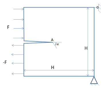
In this test case, crack-growth in a notched single edge system is considered. The system is subjected to equal and opposing forces applied on the top and bottom halves of the cracked edge so that the crack grows under pure shear conditions. The initial crack-growth angle at the crack tip is numerically calculated and compared against the analytical solution.
| Material Properties | Geometric Properties | Loading |
|---|---|---|
|
Young’s modulus, E = 100 MPa Poisson’s ratio, ν = 0.0 Crack growth criterion, PSMAX = 0.5 MPa | H = 10 mm | Nodal force, F = 0.42 N |
Analysis Assumptions and Modeling Notes
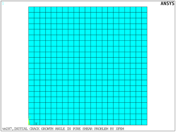
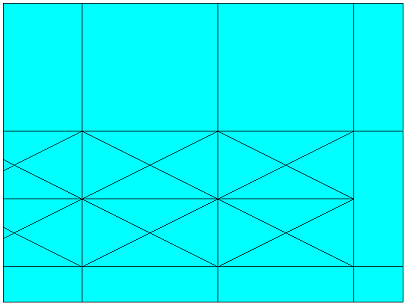
The problem is solved using 2D PLANE182 elements with plane strain behavior. The initial crack is defined using the XFENRICH and XFDATA commands so that the crack cuts through a set of elements in the middle of the left edge of the model. The bottom right corner of the plate is fixed in all degrees of freedom, and UX is constrained on the top right corner of the plate.
The crack-growth criterion used here is the maximum circumferential stress criterion. From the linear elastic crack tip asymptotic solutions shown in the reference, the circumferential stress can be evaluated in two ways:
Find the position where
 is maximum ahead of the crack tip
Find where
 ahead of the crack tip and choose the value of
  at this location.
Both methods should yield the same results. However, they may yield slightly different results due to descretization.
The fracture criterion used in the input file is based on the second evaluation method described above. PSMAX is specified on the TB,CGCR command. The CINT command is used to compute the criterion at the specified location, and the CGROW command is used to specify the XFEM method to compute the initial crack-growth angle at the crack tip.
Figure 501: Problem Sketch of a Crack Element Showing Crack Angle (α) and PHI value (c) at Node N and Half of the Element Size (a)
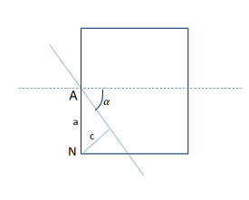
POST1 is used to evaluate the initial crack-growth angle. The PHI value (signed normal distance of the node from the crack) at node N that is closest to the newly cracked segment is obtained using the *GET command, and the initial crack-growth angle is evaluated using the formula:

where
| α = the initial crack-growth angle |
| c = PHI value at node N |
| a = half the element size |