VM176
VM176
Frequency Response of Electrical Input Admittance
Overview
Test Case
A composite piezoelectric transducer is made of a piezoceramic (NEPEC 6), aluminum, and an adhesive layer. Electrical terminals are attached to electroded surfaces of the piezoceramic where a potential V is applied. Determine the terminal input admittance Y over a frequency range spanning the first natural frequency.
| Material Properties | Geometric Properties | Loading | |||||||||||||||
|---|---|---|---|---|---|---|---|---|---|---|---|---|---|---|---|---|---|
|
|
|
Constitutive Matrices
NEPEC 6 "Stiffness" Matrix [c] x 10-10 N/m2
NEPEC 6 Piezoelectric Matrix [e] C/m2
NEPEC 6 Dielectric Matrix [εr]
Analysis Assumptions and Modeling Notes
The transducer has circumferential symmetry and is symmetric about the midplane, so the model is reduced to a single wedge of elements with an additional symmetry plane at z = 0. No internal losses (damping) are assumed. The top surface of the piezoceramic is electroded, resulting in an equipotential surface. The nodes modeling the surface have their voltage DOF coupled so that the applied potential load can be conveniently placed on a single node. The 1 volt potential load translates into a 0.5 volt potential gradient across the piezoceramic for the 1/2 symmetry model.
The TEMP and MAG degrees of freedom of SOLID5 are not used in this analysis.
Admittance Y is calculated as I/V where I is the current and
V is the applied potential. The current I is related to the accumulated
charge on the electrode surface as I = jωΣQi, where ω is the operating frequency, j is
and ΣQi is
the summed nodal charge (nodal reaction load). Since the nodal potentials
are coupled, only the reaction "load" from the single node where the
voltage is applied is required for the calculation. A series of calculations
are made between 20 kHz and 54 kHz in POST26, which span the first
natural frequency (
44 kHz). The
problem is first solved using SOLID5 elements
and then using SOLID186 and SOLID226 elements.
Results Comparison
| Target[1] | Mechanical APDL [2] | Ratio | |
|---|---|---|---|
| SOLID5 | |||
| Y, mmhos @ 20kHz | .41 | .43 | 1.047 |
| Y, mmhos @ 35kHz | .90 | .96 | 1.063 |
| Y, mmhos @ 42kHz | 2.0 | 2.8 | 1.400 |
| Y, mmhos @ 45kHz | 0.0 | -1.74 | 0.000 |
| Y, mmhos @ 50kHz | .39 | .32 | 0.833 |
| Y, mmhos @ 54kHz | .65 | .63 | 0.962 |
| SOLID226 | |||
| Y, mmhos @ 20kHz | .41 | .43 | 1.056 |
| Y, mmhos @ 35kHz | .90 | .98 | 1.086 |
| Y, mmhos @ 42kHz | 2.0 | 3.48 | 1.741 |
| Y, mmhos @ 45kHz | 0.00 | -1.13 | 0.000 |
| Y, mmhos @ 50kHz | .39 | .37 | 0.961 |
| Y, mmhos @ 54kHz | .65 | .66 | 1.008 |
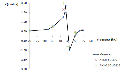
The experimentally measured values are presented in graphical form in the reference. The results tabulated here are obtained from interpolation of the graphical data.
Displayed graphically in Figure 264: Electrical Input Admittance vs. Frequency using SOLID5 and SOLID226 Elements.


