VM197
VM197
Rotating Elastic System
Overview
| Reference: | Michael I. Friswell, John E. T. Penny, Seamus D. Garvey, Arthur W. Lees. “Dynamics of Rotating Machines.” 2010: 423-429. |
| Analysis Type(s): |
Static Analysis (ANTYPE = 0) Modal and Linear Perturbation Modal Analysis (ANTYPE = 2) |
| Element Type(s): |
Structural Mass Element (MASS21) Spring-Damper Elements (COMBIN14) |
| Input Listing: | vm197.dat |
Test Case
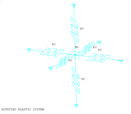
An elastic system rotates at a fixed distance around an axis. The elastic system consists of a point mass mounted at the center of six springs: two in the radial, two in the circumferential, and two in the axial direction. The mass is located between each pair of springs.
As the system rotates about the axis, the mass moves radially outward and the circumferential and axial springs develop second-order radial components of restoring force. Two cases are examined. In Case 1, linear behavior is assumed; the second-order contributions to the radial force are ignored. In Case 2, the second-order contributions are accounted for in a nonlinear analysis.
Static and modal analyses with multiple load steps are performed for both cases to determine the equilibrium displacements, stability threshold, and Campbell diagram of the system.
| Case 1 | Case 2 | |
|
Kx = 2e4 Ky = 1e5 Kz = 2.5e4 Mass = 0.2 Radius = 0.2 |
Kx = 1.2e5 Ky = 1.5e5 Kz = 1.8e5 Mass = 0.2 Radius = 0.2 | |
| Loading: Rotational Velocities (rpm) | ||
| Static Analysis | Modal Analysis |
Static Analysis and Linear Perturbed Modal Analysis |
| 0 | 0 - 8000 |
1000, 2000, 3000,…9000 |
| 500 | ||
| 1000 | ||
| 8000 | ||
Analysis Assumptions and Modeling Notes
The elastic system is modeled with the MASS21 element at the center of COMBIN14 elements (Figure 301: Elastic Structure – Mass-Springs). One end of each spring is connected to the point mass and the other end is fixed. Case 1 uses COMBIN14 as 1D longitudinal spring elements (ignoring the second-order contributions), and Case 2 uses COMBIN14 as 3D longitudinal spring elements (accounting for the second-order contributions).
In both cases, a static analysis is performed first to determine the equilibrium displacements of the point mass at different rotational speeds. After the static analysis, further analysis is performed:
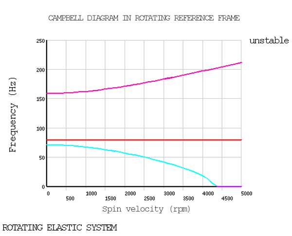
Case 1: A linear static analysis is performed first, followed by a modal analysis using the damped method. Natural frequencies of in-plane modes are determined and compared with the analytical solution.
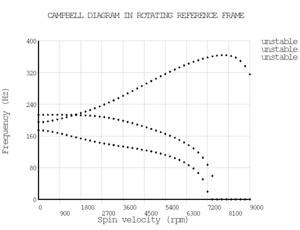
Case 2: A nonlinear static analysis is performed first, followed by a linear perturbation modal analysis.
For all analyses, the Coriolis effect is applied to the rotating structure (CORIOLIS).
The Campbell procedure (CAMPBELL) is used for both cases to determine the frequencies and to plot the Campbell diagram (PLCAMP). To determine the stability threshold with better accuracy, a large number of load steps is specified.
Results Comparison
| Case 1: | |||
|---|---|---|---|
| Target | Mechanical APDL | Ratio | |
| Equilibrium Displacements | |||
| 0 | 0.0000 | 0.0000 | 1.000 |
| 500 | 0.0005 | 0.0005 | 1.000 |
| 1000 | 0.0022 | 0.0022 | 1.000 |
| 8000 | 0.4708 | 0.4708 | 1.000 |
| First Natural Frequencies (Hz) | |||
| 0 | 71.1800 | 71.1763 | 1.000 |
| 500 | 70.2100 | 70.2088 | 1.000 |
| 1000 | 67.4000 | 67.3960 | 1.000 |
| 8000 | 0.0000 | 0.0000 | 1.000 |
| Second Natural Frequencies (Hz) | |||
| 0 | 159.1500 | 159.1549 | 1.000 |
| 500 | 160.0200 | 160.0187 | 1.000 |
| 1000 | 162.5100 | 162.5106 | 1.000 |
| 8000 | 259.5700 | 259.5704 | 1.005 |
| Stability Threshold (rpm) | |||
| SPEED | 4271.0000 | 4312.5000 | 0.990 |
| Case 2: | |||
|---|---|---|---|
| Target | Mechanical APDL | Ratio | |
| Equilibrium Displacements | |||
| 1000 | 0.0015 | 0.0015 | 1.000 |
| 2000 | 0.0060 | 0.0060 | 1.000 |
| 3000 | 0.0134 | 0.0134 | 1.000 |
| 4000 | 0.0231 | 0.0231 | 1.000 |
| 5000 | 0.0342 | 0.0342 | 1.000 |
| 6000 | 0.0465 | 0.0465 | 1.000 |
| 7000 | 0.0602 | 0.0602 | 1.000 |
| 8000 | 0.0758 | 0.0758 | 1.000 |
| 9000 | 0.0939 | 0.0939 | 1.000 |
| Stability Threshold (rpm) | |||
| SPEED | 7250.0000 | 7300.0000 | 0.993 |