VM198
VM198
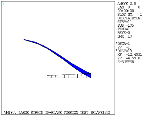
Large Strain In-plane Torsion Test
Overview
Test Case
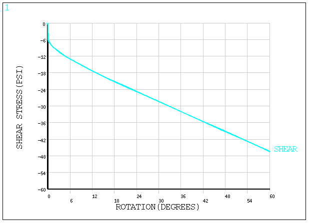
A hollow, thick-walled, long cylinder made of an elastoplastic material is under an in-plane torsional loading which causes the inner surface of the cylinder to undergo a rotation of 60°. Find the maximum shear stress (τmax) developed at the inner surface at the end of loading.

| Material Properties | Geometric Properties | Loading | ||||||||
|---|---|---|---|---|---|---|---|---|---|---|
|
|
|
Analysis Assumptions and Modeling Notes
The problem is solved for the following cases:
| Case 1: Using PLANE182 elements with plane strain element behavior |
| Case 2: Using SOLID185 elements |
| Case 3: Using PLANE183 elements with plane strain element behavior |
| Case 4: Using PLANE182 elements with torsion |
| Case 5: Using SOLID185 elements extruded from PLANE182 element solution with torsion using MAP2DTO3D |
| Case 6: Using PLANE183 elements with torsion |
| Case 7: Using SOLID186 elements extruded from PLANE183 element solution with torsion using MAP2DTO3D |
The plasticity is modeled using the bilinear isotropic hardening rule. The plane strain condition is assumed for cases 1 and 3 along the length of the cylinder. Due to the axisymmetric loading, only a small portion (3° span) of the cross-section is modeled for cases 1, 2, and 3 using ten elements. Nodal rotations and displacement couplings for cases 1, 2, and 3 are employed to ensure the circumferential symmetry in the deformed configuration. In addition, a character parameter for degrees of freedom is used in the CP commands and in the macro SOLD for cases 1, 2, and 3.
Since the modeling and loading is axisymmetric, the global X-direction represents the radial direction, the global Y-direction represents the axial direction, and the negative of the global Z-direction normal and into the 2D X-Y plane rotated about the global Y-axis represents the circumferential or hoop direction.
For cases 4 and 6, 40 elements along the radial direction are used to model the cut section on the 2D X-Y plane with only one layer of elements required along the axial direction. The ROTY rotation degrees of freedom available with PLANE182 and PLANE183 axisymmetric elements with torsion are used to model the high 60° twist of the inner radial surface into the X-Y plane (or hoop direction). MAP2DTO3D is then used to map the results from the 2D model to the 3D model for cases 5 and 7.
The maximum shear stress is calculated from the solution results for all cases. To maintain consistency with the reference solution, the maximum shear stress in a negative direction is observed.
Results Comparison
| Target | Mechanical APDL | Ratio | ||
|---|---|---|---|---|
| PLANE182 | Shear Stressmax , psi | -48.0 | -46.5 | 0.969 |
| PLANE183 | Shear Stressmax , psi | -48.0 | -45.9 | 0.956 |
| SOLID185 | Shear Stressmax , psi | -48.0 | -46.3 | 0.964 |
| PLANE182 with torsion | Shear Stressmax , psi | -48.0 | -46.4 | 0.967 |
| PLANE183 with torsion | Shear Stressmax , psi | -48.0 | -47.4 | 0.987 |
| SOLID185 extruded from PLANE182 with torsion using MAP2DTO3D | Shear Stressmax , psi | -48.0 | -47.0 | 0.979 |
| SOLID186 extruded from PLANE183 with torsion using MAP2DTO3D | Shear Stressmax , psi | -48.0 | -47.4 | 0.987 |