VM149
VM149
Residual Vector in Mode-Superposition Harmonic Analysis
Overview
| Reference: |
J.M.Dickens, J.M. Nakagawa, M.J. Wittbrodt, “ A Critique of Mode Acceleration and Modal Truncation Augmentation Methods for Modal Response Analysis”. Computers & Structures, Vol.62, pp.985-998, 1997. |
| Analysis Type(s): | Modal Analysis (ANTYPE =2) Harmonic Analysis (ANTYPE =3) |
| Element Type(s): | Spring-Damper (COMBIN14) Structural Mass (MASS21) |
| Input Listing: | vm149.dat |
Test Case
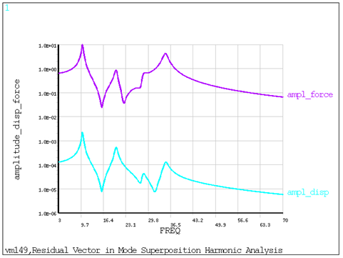
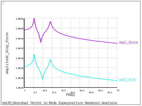
A mode-superposition harmonic analysis is performed on a spring-mass model for two cases:
| Case 1: Extracting all available modes |
| Case 2: Extracting one mode and residual vector (RESVEC) |
The following values are computed for both cases and compared against the target values shown in the reference:
Peak displacement amplitude along X direction at node 4
First and second peak force amplitude for the spring element
Frequency corresponding to first peak displacement and first peak force amplitudes
Because the target values are taken from figures, they are reported to an appropriate accuracy in the results comparison section. The modal truncation (MT) method shown in the reference corresponds to the residual vector method (Case 2).
| Material Properties | Geometric Properties | Loading | |||||||
|---|---|---|---|---|---|---|---|---|---|
|
|
|
Analysis Assumptions and Modeling Notes
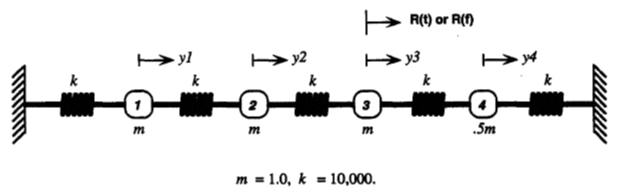
The spring-mass model is represented using 2D COMBIN14 and 2D MASS21 elements without rotary inertia. The X and Y axis of the spring model are inverted from the reference to model it along global X axis. The model is fixed at both the ends, and displacement along the Y direction is constrained on all nodes. In order to obtain four distinct modes, the mass at node 5 is set to half the value of the other three masses defined at nodes 2, 3, and 4. A modal analysis is performed first using the Block Lanczos eigensolver. A mode-superposition harmonic analysis is then performed with an excitation frequency range of 3-70 Hz and a force load along the X direction at node 4. A damping ratio of 0.02 (2%) is defined using the DMPRAT command. Calculations are done in /POST26 to determine the displacement and force amplitudes. Results are retrieved using the *GET command.
Results Comparison
| Target | Mechanical APDL | Ratio | |
|---|---|---|---|
| Extracting all available modes | |||
| UX_MAX (m) | 0.00250 | 0.00226 | 1.106 |
| F_MAX (N) | 10.00000 | 10.04035 | 0.996 |
| Frequency @ UX_MAX (Hz) | 10.10000 | 10.10200 | 1.000 |
| Frequency @ F_MAX (Hz) | 10.10000 | 10.10200 | 1.000 |
| F_MAX2 (N) | 4.50000 | 4.28867 | 1.049 |
| Extracting one mode and Residual Vector | |||
| Residual Mode | 21.8650 | 21.86523 | 1.000 |
| UX_MAX (m) | 0.00250 | 0.00226 | 1.106 |
| F_MAX (N) | 10.00000 | 10.05002 | 0.995 |
| Frequency @ UX_MAX (Hz) | 10.10000 | 10.10200 | 1.000 |
| Frequency @ F_MAX (Hz) | 10.10000 | 10.10200 | 1.000 |
| F_MAX2(N) | 4.50000 | 4.72924 | 0.952 |