Tensile test simulations are performed on the models having the dimensions shown in part (a) of the following figure:
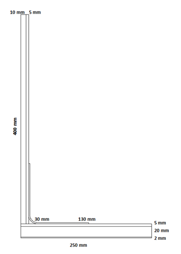
Dimensions are based on the specimen used in the reference study.[4]
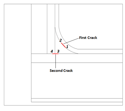
Part (b) of the figure shows the crack tip IDs.
Because plane strain is simulated, the finite element model is created using the 2D structural solid element PLANE182 (KEYOPT (1) = 2, KEYOPT(3) = 2).
The various components are bonded to each other using standard bonded contact definitions, except along the crack paths.
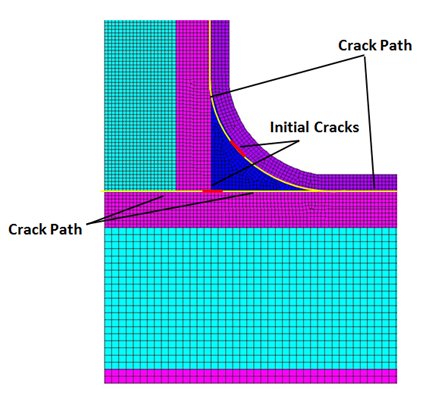
Crack paths are defined using the interface elements INTER202. To avoid crack surface interpenetrations, contact is also defined along the crack paths. The mesh around the crack paths is finer than around other sections of the model, as shown in the following figure: