Cardiovascular stent modeling involves three components:
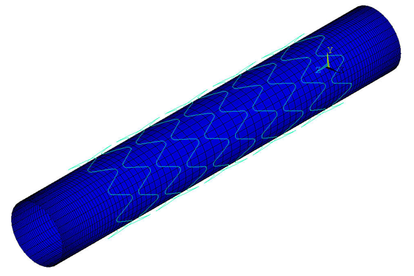
A line model of the stent is created and then meshed with 1,760 BEAM189 beam elements, as shown in the following figure:
For modeling simplicity and computational efficiency, beam elements are preferred over solid elements.
The stent assembly has a 3.5 mm diameter, a 15 mm length, and 8 crowns. The wire for constructing the stent has a circular cross-section with an outer diameter of 0.1 mm.
Although Nitinol material is commonly used for the stent, the nonlinear material behavior of Nitinol requires a separate discussion. For the purposes of this problem, therefore, the model uses linear elastic 316L steel instead.
The simplified two-layer artery and plaque model is meshed with 3D solid elements, as shown in this figure:
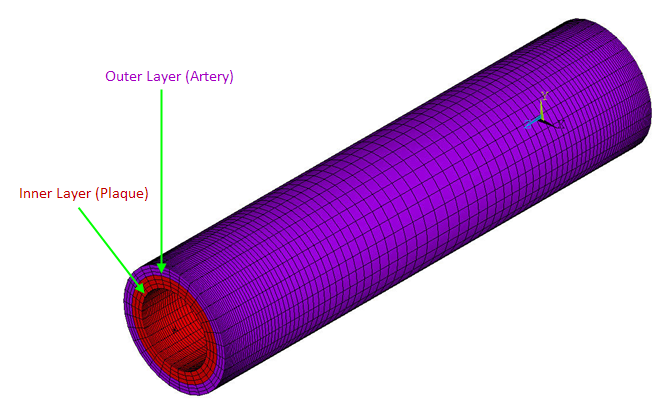
The artery layer is meshed with 9,000 SOLID185 layered structural solid elements with the simplified enhanced strain formulation (KEYOPT(2) = 3). Mixed u-P formulation (KEYOPT(6) = 1) is used to overcome the volumetric locking typically associated with incompressible biological tissue.
The plaque layer is also meshed with 9,000 SOLID185
elements. Full integration with the
 method is used for the plaque elements, as the material of the
calcified plaque is considered to be linear elastic.
method is used for the plaque elements, as the material of the
calcified plaque is considered to be linear elastic.
A coincident mesh is created at the artery-plaque interface to enforce a secure bond between the artery and the plaque.
Based on St. Venant’s principle, both the artery and plaque are extended by 3 mm to reduce end effects. Fine elements are used near the two ends to mitigate any convergence difficulty caused by large localized deformation.
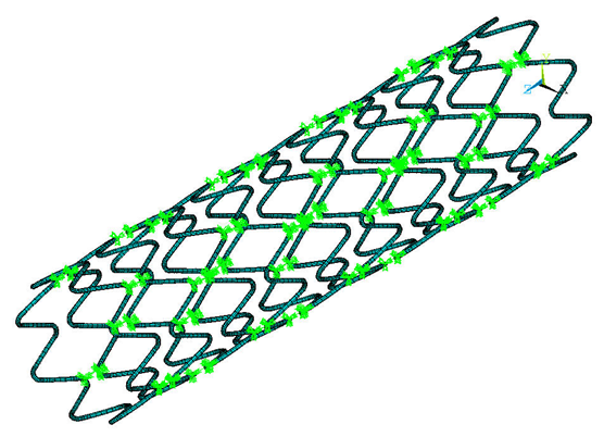
Contact between the inner plaque wall and stent from arterial contraction is modeled as line-to-surface contact.
The stent lines are meshed with CONTA177 contact elements.
A Lagrangian multiplier method on contact normals and penalty tangent method on target normals is used (KEYOPT(2) = 3), along with automatic bisection (KEYOPT(7) = 1) and standard contact behavior (KEYOPT(12) = 0).
The inner plaque wall surface is meshed with TARGE170 target elements. Zero-friction behavior is assumed.[1]
The following figure illustrates the stent-plaque contact: