


Following is an axisymmetric model of the seal components, an elastomer o-ring and a plastic cap. The rigid surface on the right represents the groove, and the left rigid surface represents the shaft.
Figure 3.2: Sealing System and Finite Element Model
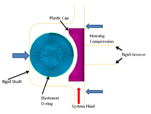 (a) Initial Configuration | |
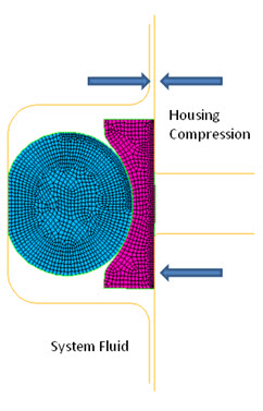 (b) End of Housing Compression |
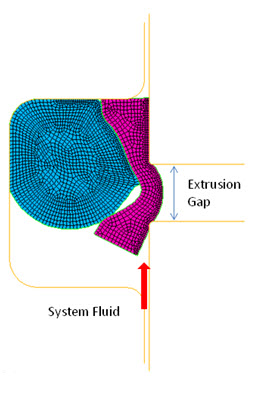 (c) End of fluid Penetration Pressure |
The geometric properties of the model are as follows:
| Property | Value |
|---|---|
| O-ring radius | 0.89 mm |
| Cap width | 0.623 mm |
| Cap height | 2.123 mm |
The following elements are used in this model:
| Element | Description | Key Option (KEYOPT) Setting | Total Number of Elements Used |
|---|---|---|---|
| PLANE182 | 2D 4-Node Structural Solid | KEYOPT(3) = 1 (axisymmetric behavior) | 2065 |
| CONTA172 | 2D 2-Node Surface-To-Surface Contact | KEYOPT(2) = 3 (Lagrange multiplier on contact normal and penalty on tangent) | 495 |
| TARGE169 | 2D Target Segment | --- | 290 |
The o-ring and cap are modeled using PLANE182 elements.
Two contact pairs are defined using CONTA172 and TARGE169 elements. One rigid-to-flexible contact pair models the contact between the entire exterior surface of seals (o-ring and cap) and the rigid surfaces, as shown by (a) in the following figure:
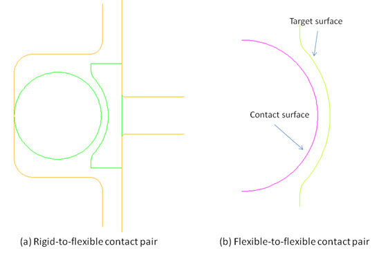
Another flexible-to-flexible contact pair models the contact between the o-ring and the cap, as shown by figure (b).
A frictional interaction is defined for the contact pairs and the friction coefficient of 0.1 is applied (via the MP command). The contact formulation used is the "Lagrange multiplier on contact-normal and penalty-on-tangent" (KEYOPT(2) = 3 on CONTA172).