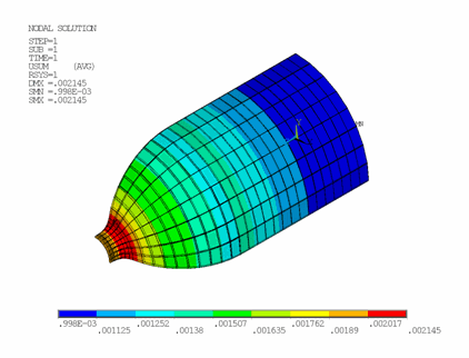
The overall deformation of the vessel is shown in the following figure:
The deformation is uniform in the hoop direction; however, a significantly nonuniform pattern is apparent in the meridian direction.
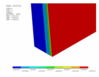
A detailed through-the-wall strain distribution in the matrix component is shown in this figure:
The improved shell formulation of SHELL281 incorporates the membrane strain effects into the curvature calculation, leading to a more accurate through-the-wall strain distribution. If the matrix is simulated with regular shell elements, strains would be largely uniform through the wall thickness.
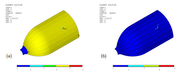
Material-specific strength limits are defined (FC) for both matrix and fiber components. The failure-criteria analysis automatically determines the layer with the maximum failure criteria value (or the most vulnerable layer that is likely to fail first). The layer number and failure-criteria value/type of the most vulnerable layer can be listed and plotted (via standard postprocessing listing and visualization commands (PRESOL and PLESOL)).
The following figure shows that the liner would most likely fail at the inlet, while the bonding material would likely fail at the fourth layer:
Similarly, according to (b) in the above figure, the fibers would fail first at the first reinforcing layer.
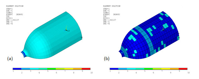
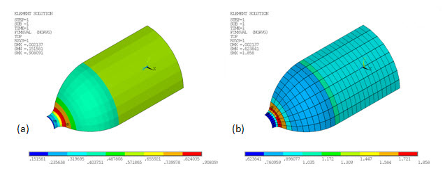
The following figure shows the type of maximum failure criteria on the matrix (a) and fiber (b) components, respectively:
Based on the value of maximum failure criteria, the tank-to-inlet transition region (b) is easily identified as the critical location for the reinforcing fibers (shown by (b) in the following figure):
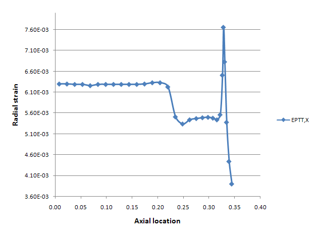
Consistent with the failure criteria analysis results, the fiber strain distribution also shows a spike in this transition region:
The results indicate that a design modification, either in the liner shape or fiber orientation, is necessary to further strengthen the fibers in this area.
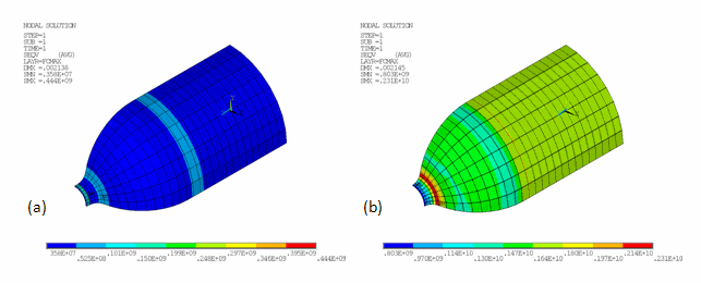
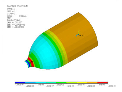
Strains, stresses, and other solution items at the layer of maximum failure criteria can be inspected (LAYER,FCMAX, followed by postprocessing listing and visualization commands (PRESOL and PLESOL)). The following figure shows the equivalent stresses at the layer of maximum failure criteria in the matrix and fiber components, respectively:
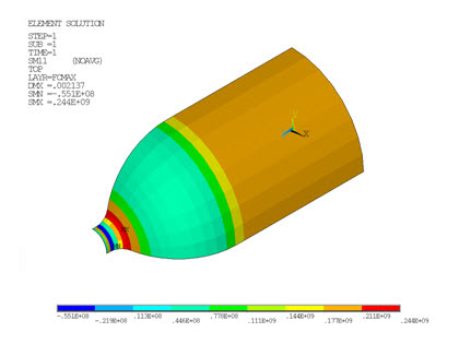
Linearized stresses are commonly cited in boiler and pressure vessel codes and standards. The program computes the linearized stresses, including membrane, bending, and peak stresses, and stores them as the SMISC quantities for current-technology shell and solid-shell elements. These quantities can be retrieved during postprocessing (ETABLE or *GET) for further inspection and code-compliance verification. The following two figures show the membrane and bending stress, respectively, of the matrix component


